| Last Modified: 11-27-2007 | 1.6 J | |
| Service Category: Brake | Section: Brake Control/Dynamic Control System | |
| Model Year: 2008 | Model: LX570 | Doc ID: RM000001DXU00JX |
| Title: BRAKE CONTROL / DYNAMIC CONTROL SYSTEMS: VEHICLE STABILITY CONTROL SYSTEM: DESCRIPTION (2008 LX570) | ||
|
TC and CG Terminal Circuit |
DESCRIPTION
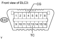
DTC output mode is set by connecting terminals TC and CG of the DLC3.
The DTCs are output to the multi-information display, and output by the blinking of the ABS warning light.
WIRING DIAGRAM
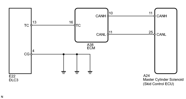
HINT:
When each warning light stays blinking, a ground short in the wiring of terminal TC of the DLC3 or an internal ground short in each ECU is suspected.
INSPECTION PROCEDURE
NOTICE:
When replacing the master cylinder solenoid, perform zero point calibration
 .
.
PROCEDURE
|
1. |
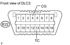
INSPECT DLC3 (DLC3 (TC) - DLC3 (CG)) |
|
(a) Turn the engine switch on (IG). |
(b) Measure the voltage according to the value(s) in the table below.
Standard Voltage:
|
Tester Connection |
Switch Condition |
Specified Condition |
|---|---|---|
|
E22-13 (TC) - E22-4 (CG) |
Engine switch on (IG) |
11 to 14 V |
|

|
2. |
CHECK CAN COMMUNICATION LINE |
(a) Turn the engine switch off.
(b) Connect the Techstream to the DLC3.
(c) Turn the engine switch on (IG) and the Techstream on.
(d) Select "CAN Bus Check" from the System Selection Menu screen, and follow the prompts on the screen to inspect the CAN Bus.
OK:
"CAN Bus Check" indicates no malfunctions in CAN communication.
|
|
3. |
CHECK DTC (for CAN Communication System) |
(a) Turn the engine switch off.
(b) Connect the Techstream to the DLC3.
(c) Turn the engine switch on (IG) and the Techstream on.
(d) Check for DTCs
.
Result
|
Result |
Proceed to |
|---|---|
|
CAN system DTC is not output. |
A |
|
CAN system DTC is output. |
B |
|
|
4. |
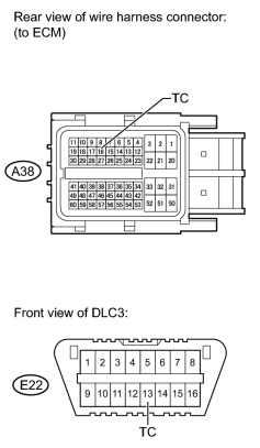
CHECK HARNESS AND CONNECTOR (ECM - DLC3 (TC)) |
|
(a) Turn the engine switch off. |
(b) Disconnect the A38 ECM connector.
(c) Measure the resistance according to the value(s) in the table below.
Standard Resistance:
|
Tester Connection |
Condition |
Specified Condition |
|---|---|---|
|
A38-16 (TC) - E22-13 (TC) |
Always |
Below 1 Ω |
|
|
5. |
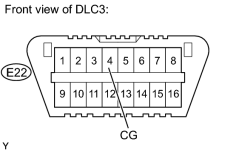
CHECK HARNESS AND CONNECTOR (DLC3 (CG) - BODY GROUND) |
|
(a) Measure the resistance according to the value(s) in the table below. Standard Resistance:
|
|
|
6. |
CHECK ECM (DLC3 (TC) INPUT) |
|
(a) Using SST, connect terminals TC and CG of the DLC3. |
(b) Check that the malfunction indicator lamp is blinking.
Result
|
Result |
Proceed to |
|---|---|
|
MIL is blinking. |
A |
|
MIL is not blinking. |
B |
|
|
7. |
CHECK DTC (for CAN Communication System) |
(a) Turn the engine switch off.
(b) Connect the Techstream to the DLC3.
(c) Turn the engine switch on (IG) and the Techstream on.
(d) Check for DTCs
.
Result
|
Result |
Proceed to |
|---|---|
|
CAN system DTC is not output. |
A |
|
CAN system DTC is output. |
B |
|

|

|