- Hydraulic brake booster pump motor
- Hydraulic brake booster pump motor circuit
- Accumulator pressure sensor
| Last Modified: 11-27-2007 | 1.6 C | |
| Service Category: Brake | Section: Brake Control/Dynamic Control System | |
| Model Year: 2008 | Model: LX570 | Doc ID: RM000001EA900LX |
| Title: BRAKE CONTROL / DYNAMIC CONTROL SYSTEMS: VEHICLE STABILITY CONTROL SYSTEM: DESCRIPTION (2008 LX570) | ||
|
DTC |
C1252/52 |
Brake Booster Pump Motor on Time Abnormally Long |
DESCRIPTION
The motor relay (semiconductor relay) is built into the master cylinder solenoid and drives the pump motor based on a signal from the skid control ECU.
|
DTC Code |
DTC Detection Condition |
Trouble Area |
|---|---|---|
|
C1252/52 |
The motor operates for 3 minutes or more. |
|
HINT:
The pump motor continues operation for the first 3 minutes, then repeats start and stop.
WIRING DIAGRAM
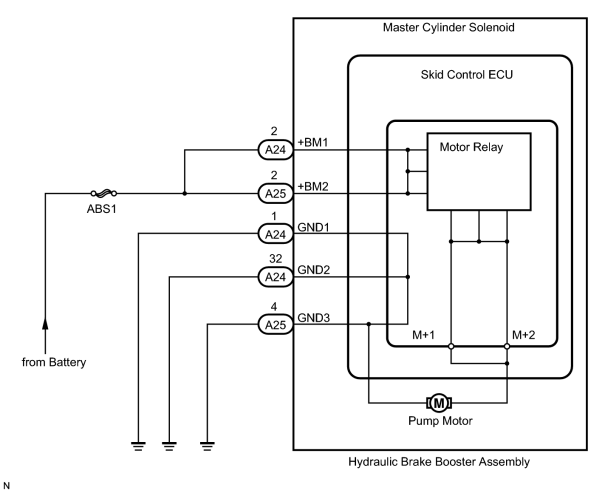
INSPECTION PROCEDURE
NOTICE:
When replacing the hydraulic brake booster assembly (master cylinder solenoid), perform zero point calibration
 .
.
HINT:
When C1253/53, C1254/54, or C1256/56 is output together with C1252/52, inspect and repair the trouble area indicated by C1253/53, C1254/54, or C1256/56 first.
PROCEDURE
|
1. |
CHECK PUMP MOTOR OPERATION |
(a) Turn the engine switch off.
(b) Depress the brake pedal more than 20 times.
(c) Turn the engine switch on (IG).
(d) Check how the pump motor operates.
Result
|
Result |
Proceed to |
|---|---|
|
Pump motor does not operate. |
A |
|
Pump motor operates continuously, and does not stop. |
B |
|
Pump motor operates intermittently. |
C |
|
Pump motor operates, then stops. |
D |
|

|
2. |
CHECK CONNECTION OF PUMP MOTOR WIRE HARNESS |
(a) Remove the hydraulic brake booster assembly
.
(b) Using a screwdriver, remove the 2 plugs from the hydraulic brake booster assembly
.
(c) Check the tightening torque of the 2 screws which tighten the wire harness connecting the hydraulic brake booster assembly and brake booster pump
.
OK:
The harness is tightened to the specific torque.
Torque: 2.9 N·m (30 kgf·cm, 26 in·lbf)
|
|
3. |
CHECK RESISTANCE OF PUMP MOTOR WIRE HARNESS |
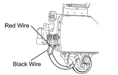
|
(a) Using a screwdriver, remove the 2 screws and pull the wire harness from the hydraulic brake booster assembly. |
(b) Measure the resistance according to the value(s) in the table below.
Standard Resistance:
|
Tester Connection |
Condition |
Specified Condition |
|---|---|---|
|
Red wire terminal - Black wire terminal |
Always |
2 Ω |
|
|
4. |
READ VALUE USING TECHSTREAM (ACCUMULATOR SENSOR) |
(a) Connect the Techstream to the DLC3.
(b) Turn the engine switch on (IG) and turn the Techstream on.
(c) Enter the following menus: Chassis / ABS/VSC/TRAC / Data List.
ABS/VSC/TRAC
|
Tester Display |
Measurement Item/Range |
Normal Condition |
Diagnostic Note |
|---|---|---|---|
|
Accumulator Sensor |
Accumulator pressure sensor reading/min.: 0 V, max.: 5 V |
3.58 to 5 V |
If the value is constant regardless of the pump operation, an accumulator pressure sensor malfunction is suspected. |
(d) Check the accumulator output value.
Result
|
Result |
Proceed to |
|---|---|
|
Output value is within the "Normal Condition" range. |
A |
|
Output value is out of the "Normal Condition" range. |
B |
|
Output value is constant regardless of pump operation. |
C |
|
|
5. |
RECONFIRM DTC |
(a) Clear the DTC
.
(b) Turn the engine switch off.
(c) Turn the engine switch on (IG).
(d) Wait for more than 5 minutes.
(e) Check if the same DTC is output
.
HINT:
Reinstall the sensors, connectors, etc. and restore the previous vehicle conditions before rechecking for DTCs.
Result
|
Result |
Proceed to |
|---|---|
|
DTC is output. |
A |
|
DTC is not output. |
B |
|

|

|