| Last Modified: 11-27-2007 | 1.6 N | |
| Service Category: Suspension | Section: Alignment/Handling Diagnoses | |
| Model Year: 2008 | Model: LX570 | Doc ID: RM000001V4300KX |
| Title: ALIGNMENT / HANDLING DIAGNOSIS: FRONT WHEEL ALIGNMENT: ADJUSTMENT (2008 LX570) | ||
ADJUSTMENT
NOTICE:
For vehicles equipped with VSC, if wheel alignment has been adjusted, and if suspension or underbody components have been removed/installed or replaced, be sure to perform the following initialization procedure in order for the system to function normally:
- Check that the steering wheel is in the centered position.
- Disconnect the negative battery terminal for more than 2 seconds.
- Reconnect the negative battery terminal.
-
Perform zero point calibration of the yaw rate and deceleration sensor and test mode inspection
 .
.
1. INSPECT TIRE
(a) Inspect the tires
.
2. INSPECT VEHICLE HEIGHT
NOTICE:
Before inspecting the wheel alignment, adjust the vehicle height to the specification.
|
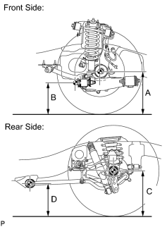
(a) Press down on the vehicle several times to stabilize the suspension, and then measure the vehicle height. Standard Vehicle Height (Unloaded Vehicle):
Measuring points: A Ground clearance of the front drive shaft center B Ground clearance of the front adjusting cam bolt center C Ground clearance of the rear axle shaft center D Ground clearance of the rear lower control arm front side center If the vehicle height is not as specified, adjust the height by pressing down on the vehicle several times to stabilize the suspension. |
3. INSPECT CAMBER, CASTER AND STEERING AXIS INCLINATION
|
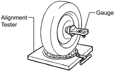
(a) Install the camber-caster-kingpin gauge or place the front wheels on the center of the wheel alignment tester. |
(b) Inspect the camber, caster and steering axis inclination.
Standard Camber Inclination (Unloaded):
|
Suspension Package Option |
Camber Inclination |
|
|---|---|---|
|
Active Height Control STD |
Camber Left - right error |
0°00' +/-45' (0.00° +/-0.75°) 45' (0.75°) or less |
Standard Caster Inclination (Unloaded):
|
Suspension Package Option |
Caster Inclination |
|
|---|---|---|
|
Active Height Control STD |
Caster Left - right error |
3°23' +/-45' (3.38° +/-0.75°) 45' (0.75°) or less |
Standard Steering Axis Inclination (Unloaded Vehicle):
|
Suspension Package Option |
Steering Axis Inclination : Reference |
|
|---|---|---|
|
Active Height Control STD |
Steering Axis |
13°00' (13.00°) |
HINT:
The steering axis inclination is a reference value.
4. ADJUST CAMBER AND CASTER
HINT:
After the camber has been adjusted, inspect the toe-in.
(a) Loosen the front adjusting cam bolt and rear adjusting cam nut.
(b) Turn the front adjusting cam and rear adjusting cam in both directions, and adjust the camber and caster to the center value.
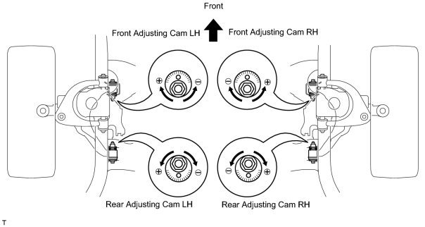
HINT:
- The camber and caster should be as close as possible to the center value.
- Make sure the difference between the left and right camber and caster is within +/-30' (0.5°).
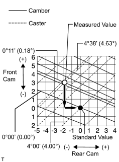
|
(c) Read the adjustment chart (example). (1) Find the wheel alignment standard value applicable for the particular model. (2) Mark the selected standard value on the adjustment chart. Standard Value (Reference):
(3) Mark the alignment value measured when the vehicle is unloaded on the adjustment chart. Measured Value (Reference):
(4) As shown in the chart, read the distance from the marked point to 0, and adjust the front and/ or rear adjusting cams accordingly. Amount to Turn Adjusting Cams (by Gradation):
|
5. INSPECT TOE-IN
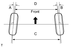
(a) Bounce the vehicle up and down at the corners to stabilize the suspension and inspect the toe-in.
Standard Toe-in (Unloaded Vehicle):
|
Item |
A + B C - D |
|---|---|
|
Toe-in (total) |
A + B: 0°00' +/-10' (0.00° +/-0.17°) C - D: 0 +/-2 mm (0 +/-0.0787 in.) |
If the toe-in is not as specified, adjust it at the rack ends.
HINT:
The toe-in can be measured using either A + B or C - D.
6. ADJUST TOE-IN
(a) Release the rack boot set clips.
(b) Loosen the tie rod end lock nuts.
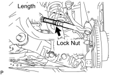
(c) Turn the right and left rack ends by an equal amount to adjust the toe-in to the center value.
|
(d) Check that the length of the right and left rack ends are approximately the same. Standard difference: 0 +/-1 mm (0 +/-0.0394 in.) or less |
(e) Tighten the tie rod end lock nuts.
Torque: 82 N·m (836 kgf·cm, 60 ft·lbf)
(f) Place the boots on the seats and install the clips.
HINT:
Make sure that the boots are not twisted.
(g) Perform the VGRS system calibration
.
7. INSPECT WHEEL ANGLE
|
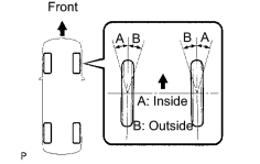
(a) Turn the steering wheel to the left and right full lock positions, and measure the turning angle. Standard Wheel Turning Angle (Unloaded Vehicle):
If the right and left inside wheel angles differ from the specified range, check the right and left rack end lengths. |
8. PLACE FRONT WHEELS FACING STRAIGHT AHEAD
9. DISCONNECT CABLE FROM NEGATIVE BATTERY TERMINAL
NOTICE:
- Disconnect the cable from the negative battery terminal for 2 seconds or more.
-
When disconnecting the cable, some systems need to be initialized after the cable is reconnected
.
w/ Navigation System:
NOTICE:
After the engine switch is turned off, the HDD navigation system requires approximately 6 minutes to record various types of memory and settings. As a result, after turning the engine switch off, wait 6 minutes or more before disconnecting the cable from the negative (-) battery terminal.
10. CONNECT CABLE TO NEGATIVE BATTERY TERMINAL
NOTICE:
When disconnecting the cable, some systems need to be initialized after the cable is reconnected
.
11. PERFORM YAW RATE AND DECELERATION SENSOR ZERO POINT CALIBRATION
(a) Perform the yaw rate and deceleration sensor zero point calibration
.

|

|