- Center differential lock switch
- Center differential lock switch circuit
- Four wheel drive control ECU
| Last Modified: 11-27-2007 | 1.6 C | |
| Service Category: Brake | Section: Brake Control/Dynamic Control System | |
| Model Year: 2008 | Model: LX570 | Doc ID: RM00000252G00EX |
| Title: BRAKE CONTROL / DYNAMIC CONTROL SYSTEMS: VEHICLE STABILITY CONTROL SYSTEM: DESCRIPTION (2008 LX570) | ||
|
DTC |
C1340/47 |
Center Differential Lock Circuit |
DESCRIPTION
When the center differential is locked, VSC control turns off and "VSC OFF" appears on the multi-information display.
|
DTC Code |
DTC Detection Condition |
Trouble Area |
|---|---|---|
|
C1340/47 |
When the terminal IG1 voltage is between 10 and 14 V and there is an open in the center differential lock circuit for 2 seconds or more. |
|
WIRING DIAGRAM
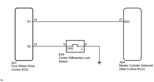
INSPECTION PROCEDURE
NOTICE:
When replacing the master cylinder solenoid, perform zero point calibration
 .
.
PROCEDURE
|
1. |
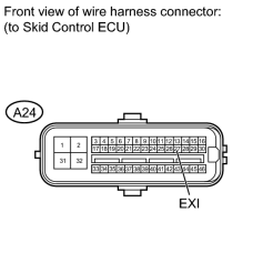
INSPECT SKID CONTROL ECU (EXI TERMINAL) |
|
(a) Disconnect the A24 skid control ECU connector. |
(b) Turn the engine switch on (IG).
(c) Measure the voltage according to the value(s) in the table below.
Standard Voltage:
|
Tester Connection |
Condition |
Specified Condition |
|---|---|---|
|
A24-27 (EXI) - Body ground |
Center differential locked (Center differential lock switch on) |
Below 1.5 V |
|
A24-27 (EXI) - Body ground |
Center differential free (Center differential lock switch off) |
11 to 14 V |
|

|
2. |
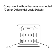
INSPECT CENTER DIFFERENTIAL LOCK SWITCH |
|
(a) Remove the center differential lock switch
|
(b) Measure the resistance according to the value(s) in the table below.
Standard Resistance:
|
Tester Connection |
Switch Condition |
Specified Condition |
|---|---|---|
|
6 (L) - 9 (CPU) |
Switch pressed and held |
Below 1 Ω |
|
Switch not pressed |
10 kΩ or higher |
|
|
3. |
INSPECT FOUR WHEEL DRIVE CONTROL ECU |
(a) Check the center differential lock system
.
|
|
4. |
CHECK HARNESS AND CONNECTOR (FOUR WHEEL DRIVE CONTROL ECU - CENTER DIFFERENTIAL LOCK SWITCH) |
(a) Disconnect the A27 four wheel drive control ECU connector.
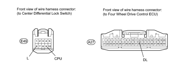
(b) Measure the resistance according to the value(s) in the table below.
Standard Resistance:
|
Tester Connection |
Condition |
Specified Condition |
|---|---|---|
|
A27-12 (DL) - E49-9 (CPU) |
Always |
Below 1 Ω |
|
A27-12 (DL) - Body ground |
Always |
10 kΩ or higher |
|
E49-6 (L) - Body ground |
Always |
Below 1 Ω |
|
|
5. |
CHECK HARNESS AND CONNECTOR (SKID CONTROL ECU - FOUR WHEEL DRIVE CONTROL ECU) |
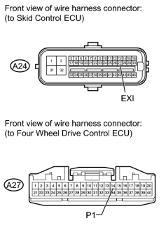
|
(a) Disconnect the A24 skid control ECU connector. |
(b) Measure the resistance according to the value(s) in the table below.
Standard Resistance:
|
Tester Connection |
Condition |
Specified Condition |
|---|---|---|
|
A24-27 (EXI) - A24-14 (P1) |
Always |
Below 1 Ω |
|
A24-27 (EXI) - Body ground |
Always |
10 kΩ or higher |
|

|

|