| Last Modified: 11-27-2007 | 1.6 G | |
| Service Category: Drivetrain | Section: Transfer/4wd/Awd | |
| Model Year: 2008 | Model: LX570 | Doc ID: RM0000038UF002X |
| Title: JF2A TRANSFER / 4WD / AWD: TRANSFER SYSTEM: INSPECTION (2008 LX570) | ||
INSPECTION
1. INSPECT INDICATOR LIGHT
(a) Check the 4LO indicator light.
(1) Start the engine.
(2) Stop the vehicle.
(3) Move the shift lever to N.
|
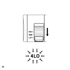
(4) Turn the transfer position switch from H4 to L4. |
(5) Check the 4LO indicator light.
OK:
|
Switch Condition |
Specified Condition |
|---|---|
|
Turned from H4 to L4 |
4LO indicator light comes on immediately or comes on after blinking |
If there is a malfunction, inspect the switch, four wheel drive control ECU and transfer shift actuator. If the system is normal, there may be a malfunction in the CAN communication system or combination meter. In that case, first check the CAN communication system
 . Then check the combination meter
.
. Then check the combination meter
.
(b) Check the center differential lock indicator light.
(1) Start the engine.
|
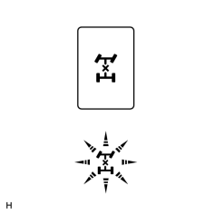
(2) Push the center differential lock switch. NOTICE:
|
(3) Check the center differential lock indicator light.
OK:
|
Switch Condition |
Specified Condition |
|---|---|
|
Pushed |
Center differential lock indicator light comes on immediately or comes on after blinking |
If there is a malfunction, inspect the switch, four wheel drive control ECU and transfer shift actuator. If the system is normal, there may be a malfunction in the CAN communication system or combination meter. In that case, first check the CAN communication system
. Then check the combination meter
.
2. INSPECT FUSE
(a) Remove the 4WD fuse from the main body ECU (cowl side junction block LH).
(b) Measure the resistance according to the value(s) in the table below.
Standard Resistance:
|
Tester Connection |
Condition |
Specified Condition |
|---|---|---|
|
4WD fuse |
Always |
Below 1 Ω |
If the fuse is blown, inspect the harness connected to the fuse for a short circuit, and repair or replace the harness or replace the fuse.
3. INSPECT TRANSFER POSITION SWITCH (BUILT INTO INTEGRATION CONTROL AND PANEL)
(a) Remove the integration control and panel
.
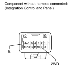
|
(b) Measure the resistance according to the value(s) in the table below. Standard Resistance:
If there is a malfunction, replace the integration control and panel. |
(c) Check the harness and connector (ECU - transfer position switch and body ground).
(1) Disconnect the A27 ECU connector.
(2) Disconnect the V4 integration control and panel connector.
(3) Measure the resistance according to the value(s) in the table below.
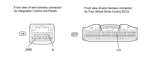
Standard Resistance:
|
Tester Connection |
Condition |
Specified Condition |
|---|---|---|
|
V4-9 (2WD) - A27-13 (LO) |
Always |
Below 1 Ω |
|
V4-9 (2WD) - Body ground |
Always |
100 kΩ or higher |
|
V4-6 (E) - Body ground |
Always |
Below 1 Ω |
If there is a malfunction, repair or replace the harness or connector.
4. INSPECT CENTER DIFFERENTIAL LOCK SWITCH
(a) Remove the center differential lock switch
.
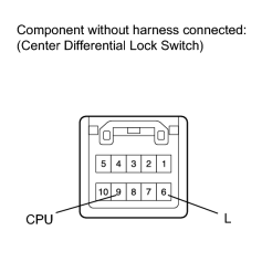
|
(b) Measure the resistance according to the value(s) in the table below. Standard Resistance:
If there is a malfunction, replace the center differential lock switch. |
(c) Check the harness and connector (ECU - center differential lock switch and body ground).
(1) Disconnect the A27 ECU connector.
(2) Disconnect the E49 center differential lock switch connector.
(3) Measure the resistance according to the value(s) in the table below.
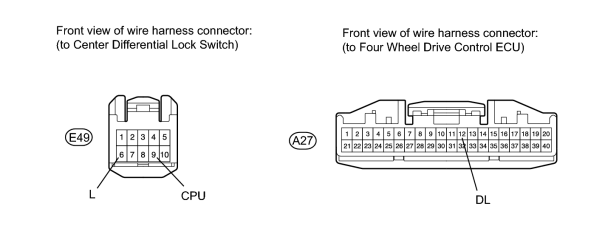
Standard Resistance:
|
Tester Connection |
Condition |
Specified Condition |
|---|---|---|
|
A27-12 (DL) - E49-9 (CPU) |
Always |
Below 1 Ω |
|
A27-12 (DL) - Body ground |
Always |
100 kΩ or higher |
|
E49-6 (L) - Body ground |
Always |
Below 1 Ω |
If there is a malfunction, repair or replace the harness or connector.
5. INSPECT TRANSFER SHIFT ACTUATOR ASSEMBLY (HIGH-LOW TRANSFER SHIFT ACTUATOR)
HINT:
After inspecting the ECU power supply or transfer position switch, check the high-low transfer shift actuator.
(a) Check the harness and connector (ECU - high-low transfer shift actuator).
(1) Disconnect the C44 actuator connector.
(2) Disconnect the A27 and A28 ECU connectors.
(3) Measure the resistance according to the value(s) in the table below.
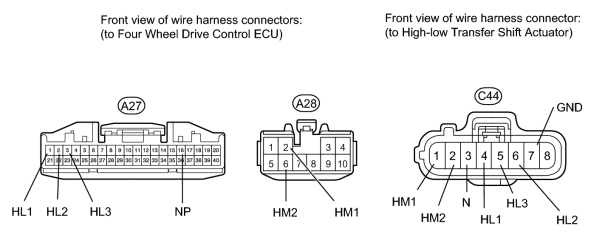
Standard Resistance:
|
Tester Connection |
Condition |
Specified Condition |
|---|---|---|
|
A27-1 (HL1) - C44-4 (HL1) |
Always |
Below 1 Ω |
|
A27-1 (HL1) - Body ground |
Always |
100 kΩ or higher |
|
A27-2 (HL2) - C44-6 (HL2) |
Always |
Below 1 Ω |
|
A27-2 (HL2) - Body ground |
Always |
100 kΩ or higher |
|
A27-3 (HL3) - C44-5 (HL3) |
Always |
Below 1 Ω |
|
A27-3 (HL3) - Body ground |
Always |
100 kΩ or higher |
|
A27-16 (NP) - C44-3 (N) |
Always |
Below 1 Ω |
|
A27-16 (NP) - Body ground |
Always |
100 kΩ or higher |
|
A28-2 (HM1) - C44-1 (HM1) |
Always |
Below 1 Ω |
|
A28-2 (HM1) - Body ground |
Always |
100 kΩ or higher |
|
A28-6 (HM2) - C44-2 (HM2) |
Always |
Below 1 Ω |
|
A28-6 (HM2) - Body ground |
Always |
100 kΩ or higher |
|
C44-7 (GND) - Body ground |
Always |
Below 1 Ω |
If there is a malfunction, repair or replace the harness or connector.
(b) Check the high-low transfer shift actuator.
(1) Turn the engine switch on (IG).
(2) Stop the vehicle.
(3) Move the shift lever to N.
(4) Check that there is an operating noise from the transfer shift actuator when the transfer position switch is turned from H4 to L4, or L4 to H4.
OK:
There is an operating noise.
HINT:
- If the actuator fork cannot move from high to low, or low to high even though there is an operating noise, there may be a mechanical malfunction in the transfer.
- If there is no operating noise, there may be a malfunction in the high-low transfer shift actuator. However, it may also be a result of a mechanical malfunction in the transfer, so inspect each part.
(5) Remove the transfer shift actuator assembly
.
(6) Check the high to low switch.
-
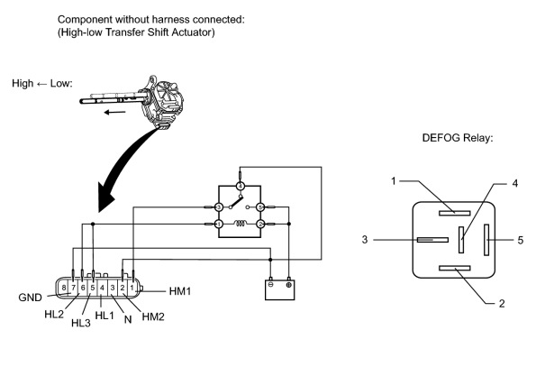
Connect lines via a relay as shown in the illustration, and check that the actuator fork moves from the high to low position.
NOTICE:
- Make sure to perform this inspection with the actuator removed from the vehicle. If this inspection is performed with the actuator installed to the vehicle, the actuator will be damaged.
- When inspecting the actuator, make sure to operate it with the lines connected via a relay. If the lines are not connected via a relay and battery voltage is directly applied to the actuator, the actuator will be damaged.
HINT:
When performing the operation described above, use the DEFOG relay.
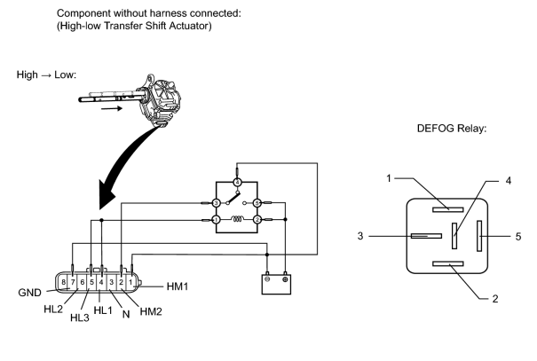
-
After the high to low switch is complete, check the neutral position detection switch and limit switch.
-
Measure the resistance according to the value(s) in the table below.
Standard Resistance:
Tester Connection
Condition
Specified Condition
3 (N) - 7 (GND)
After high to low switch is complete
100 kΩ or higher
4 (HL1) - 7 (GND)
After high to low switch is complete
100 kΩ or higher
5 (HL3) - 7 (GND)
After high to low switch is complete
100 kΩ or higher
6 (HL2) - 7 (GND)
After high to low switch is complete
Below 1 Ω
If there is a malfunction, replace the transfer shift actuator assembly.
-
Measure the resistance according to the value(s) in the table below.
(7) Check the low to high switch.
-
Connect lines via a relay as shown in the illustration, and check that the actuator fork moves from the low to high position.
NOTICE:
- Make sure to perform this inspection with the actuator removed from the vehicle. If this inspection is performed with the actuator installed to the vehicle, the actuator will be damaged.
- When inspecting the actuator, make sure to operate it with the lines connected via a relay. If the lines are not connected via a relay and battery voltage is directly applied to the actuator, the actuator will be damaged.
HINT:
When performing the operation described above, use the DEFOG relay.
-
After the low to high switch is complete, check the neutral position detection switch and limit switch.
-
Measure the resistance according to the value(s) in the table below.
Standard Resistance:
Tester Connection
Condition
Specified Condition
3 (N) - 7 (GND)
After low to high switch is complete
100 kΩ or higher
4 (HL1) - 7 (GND)
After low to high switch is complete
Below 1 Ω
5 (HL3) - 7 (GND)
After low to high switch is complete
100 kΩ or higher
6 (HL2) - 7 (GND)
After low to high switch is complete
100 kΩ or higher
If there is a malfunction, replace the transfer shift actuator assembly.
-
Measure the resistance according to the value(s) in the table below.
6. INSPECT TRANSFER SHIFT ACTUATOR ASSEMBLY (CENTER DIFFERENTIAL LOCK ACTUATOR)
HINT:
After inspecting the ECU power supply or center differential lock switch, check the center differential lock actuator.
(a) Check the harness and connector (ECU - center differential lock actuator).
(1) Disconnect the C43 actuator connector.
(2) Disconnect the A27 and A28 ECU connectors.
(3) Measure the resistance according to the value(s) in the table below.
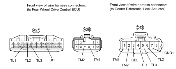
Standard Resistance:
|
Tester Connection |
Condition |
Specified Condition |
|---|---|---|
|
A27-6 (TL1) - C43-4 (TL1) |
Always |
Below 1 Ω |
|
A27-6 (TL1) - Body ground |
Always |
100 kΩ or higher |
|
A27-7 (TL2) - C43-6 (TL2) |
Always |
Below 1 Ω |
|
A27-7 (TL2) - Body ground |
Always |
100 kΩ or higher |
|
A27-8 (TL3) - C43-5 (TL3) |
Always |
Below 1 Ω |
|
A27-8 (TL3) - Body ground |
Always |
100 kΩ or higher |
|
A27-14 (P1) - C43-3 (CDL) |
Always |
Below 1 Ω |
|
A27-14 (P1) - Body ground |
Always |
100 kΩ or higher |
|
A28-7 (TM2) - C43-2 (TM2) |
Always |
Below 1 Ω |
|
A28-7 (TM2) - Body ground |
Always |
100 kΩ or higher |
|
A28-8 (TM1) - C43-1 (TM1) |
Always |
Below 1 Ω |
|
A28-8 (TM1) - Body ground |
Always |
100 kΩ or higher |
|
C43-7 (GND1) - Body ground |
Always |
Below 1 Ω |
If there is a malfunction, repair or replace the harness or connector.
(b) Check the center differential lock actuator.
(1) Turn the engine switch on (IG).
(2) Check that there is an operating noise from the transfer shift actuator when the center differential lock switch is pressed to switch from free to lock, or lock to free.
OK:
There is an operating noise.
HINT:
- If the actuator fork cannot move from free to lock, or lock to free even though there is an operating noise, there may be a mechanical malfunction in the transfer.
- If there is no operating noise, there may be a malfunction in the center differential lock actuator. However, it may also be a result of a mechanical malfunction in the transfer, so inspect each part.
(3) Remove the transfer shift actuator assembly
.
(4) Check the free to lock switch.
-
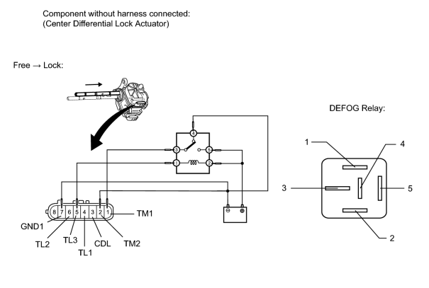
Connect lines via a relay as shown in the illustration, and check that the actuator fork moves from the free to lock position.
NOTICE:
- Make sure to perform this inspection with the actuator removed from the vehicle. If this inspection is performed with the actuator installed to the vehicle, the actuator will be damaged.
- When inspecting the actuator, make sure to operate it with the lines connected via a relay. If the lines are not connected via a relay and battery voltage is directly applied to the actuator, the actuator will be damaged.
HINT:
When performing the operation described above, use the DEFOG relay.
-
After the free to lock switch is complete, check the center differential lock detection switch and limit switch.
-
Measure the resistance according to the value(s) in the table below.
Standard Resistance:
Tester Connection
Condition
Specified Condition
3 (CDL) - 7 (GND1)
After free to lock switch is complete
Below 1 Ω
4 (TL1) - 7 (GND1)
After free to lock switch is complete
100 kΩ or higher
5 (TL3) - 7 (GND1)
After free to lock switch is complete
100 kΩ or higher
6 (TL2) - 7 (GND1)
After free to lock switch is complete
Below 1 Ω
If there is a malfunction, replace the transfer shift actuator assembly.
-
Measure the resistance according to the value(s) in the table below.
(5) Check the lock to free switch.
-
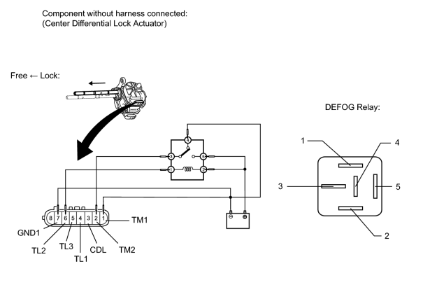
Connect lines via a relay as shown in the illustration, and check that the actuator fork moves from the lock to free position.
NOTICE:
- Make sure to perform this inspection with the actuator removed from the vehicle. If this inspection is performed with the actuator installed to the vehicle, the actuator will be damaged.
- When inspecting the actuator, make sure to operate it with the lines connected via a relay. If the lines are not connected via a relay and battery voltage is directly applied to the actuator, the actuator will be damaged.
HINT:
When performing the operation described above, use the DEFOG relay.
-
After the lock to free switch is complete, check the center differential lock detection switch and limit switch.
-
Measure the resistance according to the value(s) in the table below.
Standard Resistance:
Tester Connection
Condition
Specified Condition
3 (CDL) - 7 (GND1)
After lock to free switch is complete
100 kΩ or higher
4 (TL1) - 7 (GND1)
After lock to free switch is complete
100 kΩ or higher
5 (TL3) - 7 (GND1)
After lock to free switch is complete
Below 1 Ω
6 (TL2) - 7 (GND1)
After lock to free switch is complete
100 kΩ or higher
If there is a malfunction, replace the transfer shift actuator assembly.
-
Measure the resistance according to the value(s) in the table below.
7. INSPECT FOUR WHEEL DRIVE CONTROL ECU
HINT:
Inspect the connectors from the back side while the connectors are connected.
(a) Check the four wheel drive control ECU.
(1) Measure the resistance and voltage according to the value(s) in the table below.
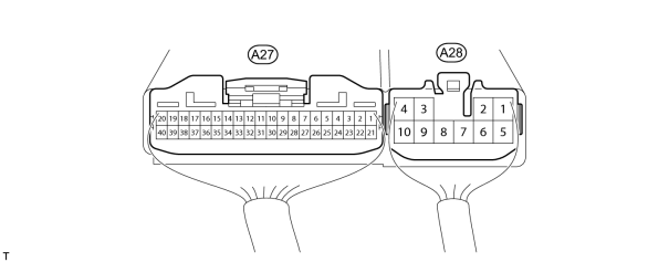
|
Tester Connection |
Terminal Description |
Condition |
Specified Condition |
|---|---|---|---|
|
A27-1 (HL1) - A28-4 (GND) |
High-low transfer shift actuator limit switch |
Engine switch on (IG) Transfer in high position |
Below 1.5 V |
|
Engine switch on (IG) Transfer in low position |
11 to 14 V |
||
|
Engine switch on (IG) Transfer in neutral position |
11 to 14 V |
||
|
A27-2 (HL2) - A28-4 (GND) |
High-low transfer shift actuator limit switch |
Engine switch on (IG) Transfer in high position |
11 to 14 V |
|
Engine switch on (IG) Transfer in low position |
Below 1.5 V |
||
|
Engine switch on (IG) Transfer in neutral position |
11 to 14 V |
||
|
A27-3 (HL3) - A28-4 (GND) |
High-low transfer shift actuator limit switch |
Engine switch on (IG) Transfer in high position |
11 to 14 V |
|
Engine switch on (IG) Transfer in low position |
11 to 14 V |
||
|
Engine switch on (IG) Transfer in neutral position |
Below 1.5 V |
||
|
A27-5 (TT) - A27-25 (TGND) |
Temperature sensor |
Engine switch on (IG) |
0 to 5 V |
|
A27-6 (TL1) - A28-4 (GND) |
Center differential lock actuator limit switch |
Engine switch on (IG) Center differential in free position |
11 to 14 V |
|
Engine switch on (IG) Center differential in lock position |
11 to 14 V |
||
|
Engine switch on (IG) Transfer in neutral position |
Below 1.5 V |
||
|
A27-7 (TL2) - A28-4 (GND) |
Center differential lock actuator limit switch |
Engine switch on (IG) Center differential in free position |
11 to 14 V |
|
Engine switch on (IG) Center differential in lock position |
Below 1.5 V |
||
|
Engine switch on (IG) Transfer in neutral position |
11 to 14 V |
||
|
A27-8 (TL3) - A28-4 (GND) |
Center differential lock actuator limit switch |
Engine switch on (IG) Center differential in free position |
Below 1.5 V |
|
Engine switch on (IG) Center differential in lock position |
11 to 14 V |
||
|
Engine switch on (IG) Transfer in neutral position |
11 to 14 V |
||
|
A27-12 (DL) - A28-4 (GND) |
Center differential lock switch |
Engine switch on (IG) Center differential lock switch is pressed and held |
Below 1.5 V |
|
Engine switch on (IG) Center differential lock switch is not pressed |
11 to 14 V |
||
|
A27-13 (LO) - A28-4 (GND) |
Transfer position switch |
Engine switch on (IG) Transfer in high position |
11 to 14 V |
|
Engine switch on (IG) Transfer in low position |
Below 1.5 V |
||
|
A27-14 (P1) - A28-4 (GND) |
Center differential lock detection switch |
Engine switch on (IG) Center differential in free position |
11 to 14 V |
|
Engine switch on (IG) Center differential in lock position |
Below 1.5 V |
||
|
A27-16 (NP) - A28-4 (GND) |
Transfer shift actuator neutral position detection switch |
Engine switch on (IG) Transfer in neutral position |
Below 1.5 V |
|
Engine switch on (IG) Transfer in high or low position |
11 to 14 V |
||
|
A27-19 (CAN+) - A27-20 (CAN-) |
CAN communication line |
Engine switch off |
54 to 69 Ω |
|
A27-21 (L4) - A28-4 (GND) |
Transfer shift actuator Low detection switch |
Engine switch on (IG) Transfer position switch in H4 position |
11 to 14 V |
|
Engine switch on (IG) Transfer position switch in L4 position |
Below 1.5 V |
||
|
A28-2 (HM1) - A28-4 (GND) |
High-low transfer shift actuator motor |
Engine switch on (IG) Transfer position switch H4 → L4 (During operation of high-low transfer shift actuator motor from high to low) |
Below 1.5 V or alternating between below 1.5 V and 11 to 14 V |
|
Engine switch on (IG) Transfer position switch L4 → H4 (During operation of high-low transfer shift actuator motor from low to high) |
11 to 14 V |
||
|
A28-3 (IG) - A28-4 (GND) |
IG power |
Engine switch on (IG) |
11 to 14 V |
|
A28-4 (GND) - Body ground |
Ground |
Always |
Below 1 Ω |
|
A28-6 (HM2) - A28-4 (GND) |
High-low transfer shift actuator motor |
Engine switch on (IG) Transfer position switch H4 → L4 (During operation of high-low transfer shift actuator motor from high to low) |
11 to 14 V |
|
Engine switch on (IG) Transfer position switch L4 → H4 (During operation of high-low transfer shift actuator motor from low to high) |
Below 1.5 V or alternating between below 1.5 V and 11 to 14 V |
||
|
A28-7 (TM2) - A28-4 (GND) |
Center differential lock actuator motor |
Engine switch on (IG) Center differential position free → lock |
Below 1.5 V or alternating between below 1.5 V and 11 to 14 V |
|
Engine switch on (IG) Center differential position lock → free |
11 to 14 V |
||
|
A28-8 (TM1) - A28-4 (GND) |
Center differential lock actuator motor |
Engine switch on (IG) Center differential position free → lock |
11 to 14 V |
|
Engine switch on (IG) Center differential position lock → free |
Below 1.5 V or alternating between below 1.5 V and 11 to 14 V |
If there is a malfunction, inspect the harnesses, connectors, transfer position switch, center differential lock switch, and transfer shift actuator assembly. If these are normal, replace the four wheel drive control ECU
.
8. INSPECT NEUTRAL SWITCHING
(a) Switch the transfer to neutral.
(1) Turn the engine switch on (IG).
(2) Move the shift lever to N.
(3) Turn the transfer position switch to H4.
(4) Make sure the center differential lock is set to the free position.
(5) Move the shift lever to P.
(6) Depress the brake pedal 3 times and do not release it on the third time.
(7) Move the shift lever to N.
(8) Depress the brake pedal 3 times.
(9) Turn the transfer position switch as follows: H4 → L4 → H4.
HINT:
The 4LO indicator light blinks at 2 second intervals (2 seconds on, 2 seconds off).
(10) Move the shift lever to P.
(11) Check that the transfer switches to neutral.
If there is a malfunction, inspect the transfer position switch, four wheel drive control ECU and transfer shift actuator. If the system is normal, there may be a malfunction in the CAN communication system. In that case, first check the CAN communication system
.
HINT:
The 4LO indicator light blinks at 2 second intervals (2 seconds on, 2 seconds off). The A/T P indicator light turns on.
(b) Release the transfer from neutral.
(1) Turn the engine switch on (IG).
(2) Move the shift lever to N.
(3) Turn the transfer position switch as follows: H4 → L4 → H4.
(4) Check that the transfer is released from neutral.
If there is a malfunction, inspect the transfer position switch, four wheel drive control ECU and transfer shift actuator. If the system is normal, there may be a malfunction in the CAN communication system. In that case, first check the CAN communication system
.
HINT:
The 4LO indicator light in the combination meter turns off. The release from neutral can be confirmed by checking that the A/T P indicator light does not turn on when the shift lever is moved to P.

|

|