- Duct sensor LH
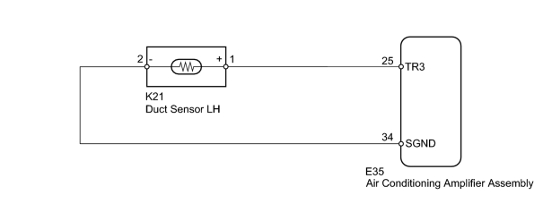
- Harness or connector (duct sensor LH)
- Air conditioning amplifier assembly
| Last Modified: 11-27-2007 | 1.6 C | |
| Service Category: Vehicle Interior | Section: Heating/Air Conditioning | |
| Model Year: 2008 | Model: LX570 | Doc ID: RM000002Q4Q009X |
| Title: HEATING / AIR CONDITIONING: AIR CONDITIONING SYSTEM: DESCRIPTION (2008 LX570) | ||
|
DTC |
B1467/67 |
Rear Air Foot Duct Sensor Circuit on Driver Side |
DESCRIPTION
The duct sensor LH (for driver side) detects the duct temperature and sends the appropriate signals to the air conditioning amplifier assembly.
|
DTC Code |
DTC Detection Condition |
Trouble Area |
|---|---|---|
|
B1467/67 |
An open or short in the duct sensor LH circuit. |
|
WIRING DIAGRAM
INSPECTION PROCEDURE
PROCEDURE
|
1. |
READ VALUE USING TECHSTREAM (DUCT SENSOR LH) |
(a) Use the Data List to check if the duct sensor LH (for driver side) is functioning properly.
Air Conditioner
|
Tester Display |
Measurement Item/Range |
Normal Condition |
Diagnostic Note |
|---|---|---|---|
|
Foot Duct Sensor (Rear D) |
Duct sensor / Min.: -12.7°C (9.14°F) Max.: 76.55°C (169.79°F) |
Actual temperature measured by duct sensor LH displayed |
Open in the circuit: -30°C (86°F). Short in the circuit: 80.6°C (177°F). |
OK:
The display is as specified in the normal condition.
|

|
2. |
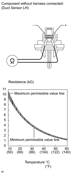
CHECK DUCT SENSOR LH |
|
(a) Remove the duct sensor LH
|

(b) Measure the resistance according to the value(s) in the table below.
Standard Resistance:
|
Tester Connection |
Condition |
Specified Condition |
|---|---|---|
|
1 (+) - 2 (-) |
10°C (50°F) |
9.4 to 10.5 kΩ |
|
15°C (59°F) |
7.5 to 8.3 kΩ |
|
|
20°C (68°F) |
6.0 to 6.5 kΩ |
|
|
25°C (77°F) |
4.8 to 5.2 kΩ |
|
|
30°C (86°F) |
3.8 to 4.2 kΩ |
|
|
35°C (95°F) |
3.1 to 3.4 kΩ |
|
|
40°C (104°F) |
2.5 to 2.8 kΩ |
|
|
45°C (113°F) |
2.0 to 2.3 kΩ |
|
|
50°C (122°F) |
1.6 to 2.0 kΩ |
|
|
55°C (131°F) |
1.3 to 1.6 kΩ |
|
|
60°C (140°F) |
1.1 to 1.4 kΩ |
NOTICE:
- Touching the sensor even slightly may change the resistance value. Hold the connector of the sensor.
- When measuring the resistance, the sensor temperature must be the same as the ambient temperature.
HINT:
As the temperature increases, the resistance decreases (See the graph).
If the resistance value is not as specified, replace the sensor.
|
|
3. |
CHECK HARNESS AND CONNECTOR (AIR CONDITIONING AMPLIFIER - DUCT SENSOR) |
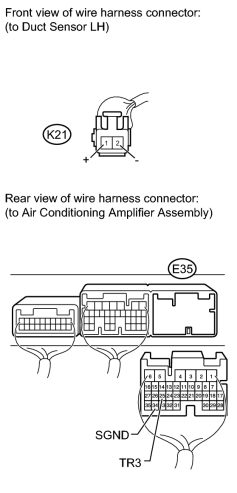
(a) Disconnect the K21 sensor connector.
(b) Disconnect the E35 amplifier connector.
(c) Measure the resistance according to the value(s) in the table below.
Standard Resistance:
|
Tester Connection |
Condition |
Specified Condition |
|---|---|---|
|
E35-25 (TR3) - K21-1 (+) |
Always |
Below 1 Ω |
|
E35-34 (SGND) - K21-2 (-) |
||
|
E35-25 (TR3) - Body ground |
Always |
0.7 to 35 kΩ |
|
E35-34 (SGND) - Body ground |
Always |
Below 1 Ω |
|

|

|