- Harness or connector
- Combination meter assembly
- Fuel suction with pump and gauge assembly
- Fuel sender gauge assembly
| Last Modified: 11-27-2007 | 1.6 C | |
| Service Category: Vehicle Interior | Section: Meter/Gauge/Display | |
| Model Year: 2008 | Model: LX570 | Doc ID: RM000002S2T00DX |
| Title: METER / GAUGE / DISPLAY: METER / GAUGE SYSTEM: DESCRIPTION (2008 LX570) | ||
|
DTC |
B1500 |
Fuel Sender Open Detected |
DESCRIPTION
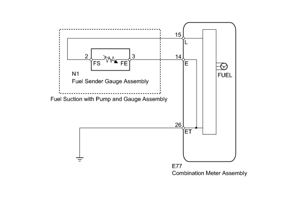
This DTC is stored when the combination meter detects a fuel sender gauge malfunction via the CAN.
|
DTC Code |
DTC Detection Condition |
Trouble Area |
|---|---|---|
|
B1500 |
When the combination meter detects a fuel sender gauge malfunction. |
|
WIRING DIAGRAM
INSPECTION PROCEDURE
PROCEDURE
|
1. |
READ VALUE USING TECHSTREAM (FUEL SENDER GAUGE) |
(a) Operate the Techstream according to the display and select the Data List
 .
.
Combination Meter
|
Tester Display |
Measurement Item/Range |
Normal Condition |
Diagnostic Note |
|---|---|---|---|
|
Fuel Input |
Fuel sender gauge (main) input signal/Min.: 0, Max.: 127.5 |
Fuel sender input value |
Unit: L |
OK:
Fuel amount value displayed on the Techstream is almost the same as needle indication.
|

|
2. |
CHECK HARNESS AND CONNECTOR (COMBINATION METER - FUEL SENDER GAUGE AND BODY GROUND) |
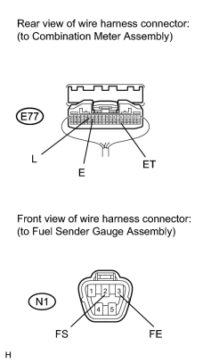
(a) Disconnect the E77 meter connector.
(b) Disconnect the N1 gauge connector.
(c) Measure the resistance according to the value(s) in the table below.
Standard Resistance:
|
Tester Connection |
Condition |
Specified Condition |
|---|---|---|
|
E77-15 (L) - N1-2 (FS) |
Always |
Below 1 Ω |
|
E77-14 (E) - N1-3 (FE) |
||
|
E77-26 (ET) - Body ground |
||
|
E77-15 (L) or N1-2 (FS) - Body ground |
Always |
10 kΩ or higher |
|
|
3. |
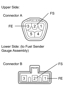
INSPECT FUEL SUCTION WITH PUMP AND GAUGE ASSEMBLY |
|
(a) Remove the fuel sender gauge
|
(b) Measure the resistance according to the value(s) in the table below.
Standard Resistance:
|
Tester Connection |
Condition |
Specified Condition |
|---|---|---|
|
A-2 (FS) - B-2 (FS) |
Always |
Below 1 Ω |
|
A-3 (FE) - B-1 (FE) |
|
|
4. |
INSPECT FUEL SENDER GAUGE ASSEMBLY |
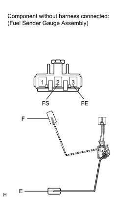
(a) Remove the fuel sender gauge
.
(b) Measure the resistance according to the value(s) in the table below.
Standard Resistance:
|
Tester Connection |
Condition |
Specified Condition |
|---|---|---|
|
2 (FS) - 3 (FE) |
Float level is F (upper) |
12 to 18 Ω |
|
Float level is E (lower) |
405 to 415 Ω |
|

|

|