| Last Modified: 11-27-2007 | 1.6 A | |
| Service Category: Engine/Hybrid System | Section: Engine Mechanical | |
| Model Year: 2008 | Model: LX570 | Doc ID: RM000002S5000EX |
| Title: 3UR-FE ENGINE MECHANICAL: CYLINDER HEAD GASKET: INSTALLATION (2008 LX570) | ||
INSTALLATION
1. INSPECT CYLINDER HEAD SET BOLT

2. INSPECT CYLINDER HEAD SUB-ASSEMBLY
3. INSTALL CYLINDER HEAD SUB-ASSEMBLY RH
(a) Check the piston protrusions for each cylinder.
(1) Clean the cylinder block with solvent.
(2) Set the piston of the cylinder to be measured to slightly ATDC.
|
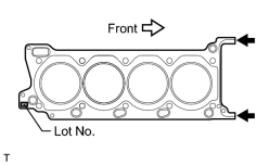
(b) Place the cylinder head gasket on the cylinder block surface with the front face of the Lot No. stamp upward. NOTICE:
|
(c) Place the cylinder head on the cylinder block.
HINT:
The cylinder head bolts are tightened in 3 progressive steps.
NOTICE:
- Ensure that no oil is on the mounting surface of the cylinder head.
- Gently place the cylinder head in order not to damage the gasket with the bottom part of the head.
(d) Apply a light coat of engine oil to the threads and under the heads of the cylinder head bolts.
|
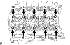
(e) Step 1: (1) Using a 10 mm bi-hexagon wrench, install and uniformly tighten the 10 cylinder head bolts with the plate washers in several steps in the sequence shown in the illustration. Torque: 36 N·m (367 kgf·cm, 27 ft·lbf) |
|
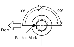
(f) Step 2: (1) Mark each cylinder head bolt head with paint as shown in the illustration. (2) Tighten the cylinder head bolts 90° in the sequence shown in step 1. |
(g) Step 3:
(1) Tighten the cylinder head bolts another 90° in the sequence shown in step 1.
(2) Check that the painting marks are now facing rearward.
|
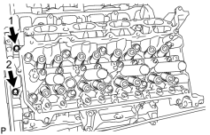
(h) Uniformly install the 2 bolts in the sequence shown in the illustration. Torque: 21 N·m (214 kgf·cm, 15 ft·lbf) |
4. INSTALL CYLINDER HEAD SUB-ASSEMBLY LH
(a) Check the piston protrusions for each cylinder.
(1) Clean the cylinder block with solvent.
(2) Set the piston of the cylinder to be measured to slightly ATDC.
|
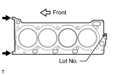
(b) Place the cylinder head gasket on the cylinder block surface with the front face of the Lot No. stamp upward. NOTICE:
|
(c) Place the cylinder head on the cylinder block.
HINT:
The cylinder head bolts are tightened in 3 progressive steps.
NOTICE:
- Ensure that no oil is on the mounting surface of the cylinder head.
- Gently place the cylinder head in order not to damage the gasket with the bottom part of the head.
(d) Apply a light coat of engine oil to the threads and under the heads of the cylinder head bolts.
|
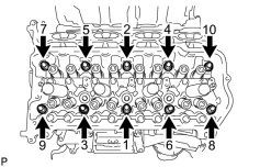
(e) Step 1: (1) Using a 10 mm bi-hexagon wrench, install and uniformly tighten the 10 cylinder head bolts with the plate washers in several steps in the sequence shown in the illustration. Torque: 36 N·m (367 kgf·cm, 27 ft·lbf) |
|
|
(f) Step 2: (1) Mark each cylinder head bolt head with paint as shown in the illustration. (2) Tighten the cylinder head bolts 90° in the sequence shown in step 1. |
(g) Step 3:
(1) Tighten the cylinder head bolts another 90° in the sequence shown in step 1.
(2) Check that the painted marks are now facing rearward.
|
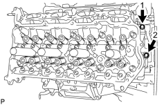
(h) Uniformly install the 2 bolts in the sequence shown in the illustration. Torque: 21 N·m (214 kgf·cm, 15 ft·lbf) |
5. INSTALL VALVE STEM CAP
6. INSTALL VALVE LASH ADJUSTER ASSEMBLY
7. INSTALL NO. 1 VALVE ROCKER ARM SUB-ASSEMBLY
8. INSTALL CAMSHAFT
(a) Install the camshaft
.
9. INSTALL EXHAUST MANIFOLD SUB-ASSEMBLY
(a) Install the exhaust manifold
.
10. CONNECT CABLE TO NEGATIVE BATTERY TERMINAL
NOTICE:
When disconnecting the cable, some systems need to be initialized after the cable is reconnected
.
11. INSPECT FOR EXHAUST GAS LEAK
12. INSPECT IGNITION TIMING
13. INSPECT ENGINE IDLE SPEED

|

|