| Last Modified: 11-27-2007 | 1.6 A | |
| Service Category: Engine/Hybrid System | Section: Intake/Exhaust | |
| Model Year: 2008 | Model: LX570 | Doc ID: RM0000031GV006X |
| Title: 3UR-FE INTAKE / EXHAUST: EXHAUST MANIFOLD: INSTALLATION (2008 LX570) | ||
INSTALLATION
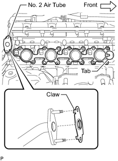
1. INSTALL EXHAUST MANIFOLD SUB-ASSEMBLY RH
|
(a) Install a new gasket to the cylinder head and a new gasket to the No. 2 air tube. HINT:
|
|
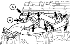
(b) Temporarily install the exhaust manifold with the 2 nuts labeled A and 8 new nuts. |
(c) Uniformly tighten the nuts that are not labeled A, and then tighten the 2 nuts labeled A.
Torque: 10 N·m (102 kgf·cm, 7 ft·lbf)
Torque: 21 N·m (214 kgf·cm, 15 ft·lbf)
|
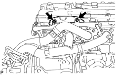
(d) Install the insulator to the exhaust manifold with the 2 nuts. Torque: 10 N·m (102 kgf·cm, 7 ft·lbf) |
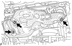
2. INSTALL NO. 1 EXHAUST MANIFOLD HEAT INSULATOR
|
(a) Install the heat insulator with the 3 bolts. Torque: 10 N·m (102 kgf·cm, 7 ft·lbf) |
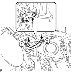
3. INSTALL NO. 1 MANIFOLD STAY
|
(a) Temporarily install the manifold stay with the 2 bolts. |
(b) Tighten the 2 bolts in the order shown in the illustration.
Torque: 40 N·m (408 kgf·cm, 30 ft·lbf)
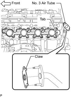
4. INSTALL EXHAUST MANIFOLD SUB-ASSEMBLY LH
|
(a) Install a new gasket to the cylinder head and a new gasket to the No. 3 air tube. HINT:
|
|
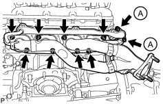
(b) Temporarily install the exhaust manifold with the 2 nuts labeled A and 8 new nuts. |
(c) Uniformly tighten the nuts that are not labeled A, and then tighten the 2 nuts labeled A.
Torque: 10 N·m (102 kgf·cm, 7 ft·lbf)
Torque: 21 N·m (214 kgf·cm, 15 ft·lbf)
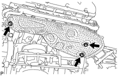
5. INSTALL NO. 2 EXHAUST MANIFOLD HEAT INSULATOR
|
(a) Install the heat insulator with the 3 bolts. Torque: 10 N·m (102 kgf·cm, 7 ft·lbf) |
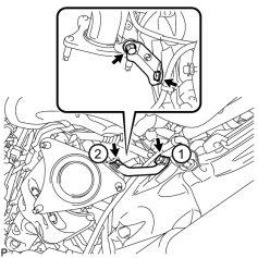
6. INSTALL NO. 2 MANIFOLD STAY
|
(a) Temporarily install the manifold stay with the 2 bolts. |
(b) Tighten the 2 bolts in the order shown in the illustration.
Torque: 40 N·m (408 kgf·cm, 30 ft·lbf)
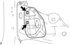
7. INSTALL PROPELLER SHAFT HEAT INSULATOR
|
(a) Install the heat insulator with the 2 bolts. Torque: 16 N·m (160 kgf·cm, 12 ft·lbf) |
8. INSTALL FRONT EXHAUST PIPE ASSEMBLY

9. INSTALL FRONT NO. 2 EXHAUST PIPE ASSEMBLY
10. INSTALL CENTER EXHAUST PIPE ASSEMBLY
11. INSTALL TAILPIPE ASSEMBLY
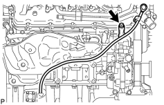
12. INSTALL ENGINE OIL LEVEL DIPSTICK GUIDE
|
(a) Apply a light coat of engine oil to a new O-ring. |
(b) Install the O-ring to the guide.
(c) Install the dipstick guide with the bolt.
Torque: 10 N·m (102 kgf·cm, 7 ft·lbf)
(d) Install the dipstick.
13. INSPECT FOR EXHAUST GAS LEAK
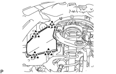
14. INSTALL FRONT FENDER APRON SEAL FRONT LH
|
(a) Install the fender apron seal with the 4 clips. |
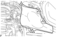
15. INSTALL FRONT FENDER APRON SEAL REAR LH
|
(a) Install the fender apron seal with the 4 clips. |
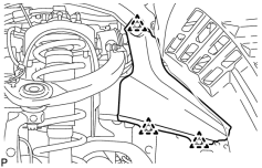
16. INSTALL FRONT FENDER APRON SEAL FRONT RH
|
(a) Install the fender apron seal with the 3 clips. |
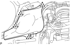
17. INSTALL FRONT FENDER APRON SEAL REAR RH
|
(a) Install the fender apron seal with the 4 clips. |
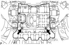
18. INSTALL NO. 2 ENGINE UNDER COVER
|
(a) Install the No. 2 engine under cover with the 2 bolts. Torque: 29 N·m (296 kgf·cm, 21 ft·lbf) |
19. INSTALL NO. 1 ENGINE UNDER COVER SUB-ASSEMBLY
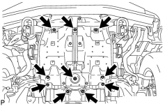
|
(a) Install the No. 1 engine under cover with the 10 bolts. Torque: 29 N·m (296 kgf·cm, 21 ft·lbf) |
20. INSTALL FRONT FENDER SPLASH SHIELD SUB-ASSEMBLY LH
21. INSTALL FRONT FENDER SPLASH SHIELD SUB-ASSEMBLY RH
22. INSTALL UPPER RADIATOR SUPPORT SEAL
23. INSTALL ENGINE ROOM SIDE COVER RH
24. INSTALL ENGINE ROOM SIDE COVER LH

|

|