| Last Modified: 11-27-2007 | 1.6 J | |
| Service Category: Vehicle Interior | Section: Meter/Gauge/Display | |
| Model Year: 2008 | Model: LX570 | Doc ID: RM000002TIQ009X |
| Title: METER / GAUGE / DISPLAY: METER / GAUGE SYSTEM: DESCRIPTION (2008 LX570) | ||
|
Meter Illumination is Always Dark |
DESCRIPTION
In this circuit, the combination meter assembly receives auto dimmer signals from the main body ECU using CAN communication lines. When the combination meter assembly receives an auto dimmer signal, it dims the meter illumination. The main body ECU determines whether it is daytime, twilight or nighttime based on the waveform transmitted from the automatic light control sensor. If the main body ECU determines that it is daytime, the ECU does not send auto dimmer signals. Therefore, the meter illumination (warning and indicator lights) will not dim even if the driver accidentally turns the light control switch to the tail or head position in the daytime.
HINT:
When the meter illumination does not dim at night, the light control rheostat is fully turned to the right (TAIL cancel switch is on), or there may be a malfunction in the automatic light control sensor, main body ECU, CAN communication system, wire harness or connector, or combination meter.
WIRING DIAGRAM
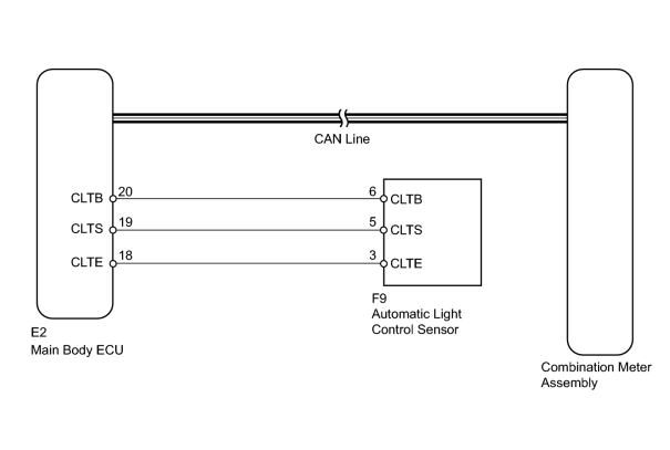
INSPECTION PROCEDURE
PROCEDURE
|
1. |
CHECK CAN COMMUNICATION SYSTEM |
(a) Check for DTCs
 .
.
Result
|
Result |
Proceed to |
|---|---|
|
DTC is not output |
A |
|
CAN communication system DTC is output |
B |
|
Lighting system DTC (B1244) is output |
C |
|

|
2. |
PERFORM ACTIVE TEST USING TECHSTREAM (DIMMER SWITCH) |
(a) Operate the Techstream according to the display and select the Active Test.
Main Body
|
Tester Display |
Test Part |
Control Range |
Diagnostic Note |
|---|---|---|---|
|
Dimmer Signal |
Illumination dimming operation |
ON or OFF |
- |
OK:
Meter illumination is dimmed when the dimmer switch is on and the Active Test "Dimmer Signal" is ON.
HINT:
Refer to the sensitivity setting in the customization table of the automatic light control system
.
|
|
3. |
REPLACE COMBINATION METER ASSEMBLY |
(a) Temporarily replace the combination meter with a new one
.
|
|
4. |
CHECK COMBINATION METER ASSEMBLY |
(a) Check that the operation of the combination meter returns to normal
.
OK:
Operation of combination meter returns to normal.
|

|

|