| Last Modified: 11-27-2007 | 1.6 J | |
| Service Category: Vehicle Interior | Section: Theft Deterrent/Keyless Entry | |
| Model Year: 2008 | Model: LX570 | Doc ID: RM000002VHD00QX |
| Title: THEFT DETERRENT / KEYLESS ENTRY: SMART ACCESS SYSTEM WITH PUSH-BUTTON START (for Entry Function): DESCRIPTION (2008 LX570) | ||
|
All Door Entry Lock/Unlock Functions and Wireless Functions do not Operate |
DESCRIPTION
When the entry operation and wireless operation door lock function does not operate, a malfunction or wave interference may be occurring in either of the following: 1) the signal communication line between the door control receiver and certification ECU (smart key ECU assembly) (line is used by entry and wireless); or 2) the door control transmitter.
WIRING DIAGRAM
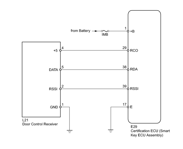
INSPECTION PROCEDURE
NOTICE:
- Before performing the inspection, check that there are no problems related to the "CAN Communication System" and "LIN Communication System".
- Check that there are no door control transmitters in the vehicle.
-
Before performing the inspection, check that DTC B1242 is not output
 .
.
PROCEDURE
|
1. |
CHECK POWER DOOR LOCK CONTROL SYSTEM |
(a) When the master switch door control switch is operated, check that the locked doors unlock
.
OK:
Locked doors unlock.
|

|
2. |
CHECK DOOR CONTROL TRANSMITTER |
(a) When another registered door control transmitter is used, check that the wireless and entry function operates normally
.
Result
|
Result |
Proceed to |
|---|---|
|
Entry function operates and door control transmitter that did not operate is electrical key transmitter |
A |
|
Entry function operates and door control transmitter that did not operate is card key* |
B |
|
Entry function does not operate |
C |
*: for Card Type
|
|
3. |
CHECK DOOR CONTROL TRANSMITTER (LED) |
(a) Check that the transmitter LED illuminates 3 times when a switch is pressed 3 times.
Result
|
Result |
Proceed to |
|---|---|
|
Transmitter LED does not illuminate 3 times when switch is pressed 3 times |
A |
|
Transmitter LED illuminates 3 times when switch is pressed 3 times |
B |
|
Transmitter LED does not illuminate second or third time |
C |
HINT:
If the transmitter LED does not illuminate the second or third time, replace the transmitter battery as it is depleted.
|
|
4. |
INSPECT TRANSMITTER BATTERY (VOLTAGE) |
(a) Electrical Key Transmitter:
|
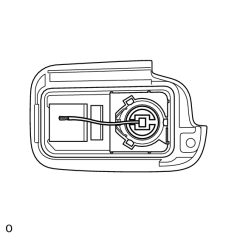
(1) Remove the battery from the electrical key transmitter that does not operate. Attach a lead wire (0.6 mm (0.0236 in.) or less in diameter including wire sheath) with tape or equivalent to the negative terminal
NOTICE:
Do not wrap the lead wire around a terminal, wedge it between terminals, or solder it. A terminal may be deformed or damaged, and the battery will not be able to be installed correctly. |
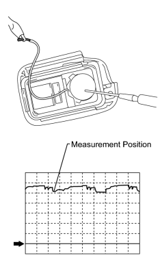
(2) Carefully pull the lead wire out from the position shown in the illustration and install the previously removed transmitter battery.
|
(3) Using an oscilloscope, check the transmitter battery voltage. HINT:
When measuring the battery voltage, while operating the lock switch of a door handle, bring the electrical key transmitter within the entry operating range to perform the measurement. For the entry operating range, refer to System Description
Standard Voltage:
|
|
|
5. |
INSPECT CARD KEY BATTERY (VOLTAGE) |
(a) Card Type Key:
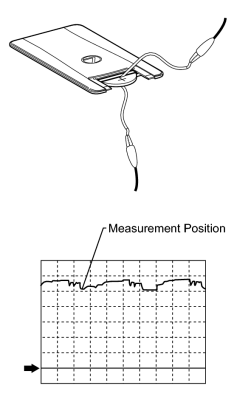
(1) Remove the battery from the card key that does not operate. Attach a lead wire to the negative and positive side of the battery with tape or equivalent
.
NOTICE:
Do not wrap the lead wire around a terminal, wedge it between the terminals, or solder it. A terminal may be deformed or damaged, and the battery will not be able to be installed correctly.
|
(2) Using an oscilloscope, check the transmitter battery voltage. HINT:
When measuring the battery voltage, while operating the lock switch of a door handle, bring the card key within the entry operating range to perform the measurement. For the entry operating range, refer to System Description
Standard Voltage:
NOTICE:
Before measuring the battery voltage, make sure that the positive side of the battery is set towards the LEXUS mark side. |
|
|
6. |
CHECK WAVE ENVIRONMENT |
(a) Bring the door control transmitter near the door control receiver, and perform a wireless and entry function operation check.
HINT:
- When the door control transmitter is brought near the door control receiver, the possibility of wave interference decreases, and it can be determined if wave interference is causing the problem symptom.
- If the inspection result is that the problem only occurs in certain locations or times of day, the possibility of wave interference is high. Also, added vehicle components may cause wave interference. If installed, remove them and perform the operation check.
OK:
Wireless and entry functions operate normally.
|
|
7. |
INSPECT FUSE (IMB) |
(a) Remove the IMB fuse from the engine room relay block.
(b) Measure the resistance according to the value(s) in the table below.
Standard Resistance:
|
Tester Connection |
Condition |
Specified Condition |
|---|---|---|
|
IMB fuse |
Always |
Below 1 Ω |
|
|
8. |
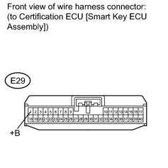
CHECK HARNESS AND CONNECTOR (CERTIFICATION ECU [SMART KEY ECU ASSEMBLY] - BATTERY) |
|
(a) Disconnect the E29 ECU connector. |
(b) Measure the resistance and voltage according to the value(s) in the tables below.
Standard Resistance:
|
Tester Connection |
Condition |
Specified Condition |
|---|---|---|
|
E29-17 (E) - Body ground |
Always |
Below 1 Ω |
Standard Voltage:
|
Tester Connection |
Condition |
Specified Condition |
|---|---|---|
|
E29-1 (+B) - Body ground |
Always |
11 to 14 V |
|
|
9. |
CHECK HARNESS AND CONNECTOR (CERTIFICATION ECU [SMART KEY ECU ASSEMBLY] - DOOR CONTROL RECEIVER AND BODY GROUND) |
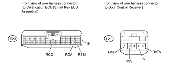
(a) Disconnect the L21 receiver connector.
(b) Disconnect the E29 ECU connector.
(c) Measure the resistance according to the value(s) in the table below.
Standard Resistance:
|
Tester Connection |
Condition |
Specified Condition |
|---|---|---|
|
E29-29 (RCO) - L21-4 (+5) |
Always |
Below 1 Ω |
|
E29-38 (RDA) - L21-5 (DATA) |
Always |
Below 1 Ω |
|
E29-39 (RSSI) - L21-2 (RSSI) |
Always |
Below 1 Ω |
|
E29-17(E) - Body ground |
Always |
Below 1 Ω |
|
L21-1 (GND) - Body ground |
Always |
Below 1 Ω |
|
E29-29 (RCO) or L21-4 (+5) - Body ground |
Always |
10 kΩ or higher |
|
E29-38 (RDA) or L21-5 (DATA) - Body ground |
Always |
10 kΩ or higher |
|
E29-39 (RSSI) or L21-2 (RSSI) - Body ground |
Always |
10 kΩ or higher |
|
|
10. |
CHECK DOOR CONTROL RECEIVER OPERATION |
(a) Temporarily replace the door control receiver with a new one
.
(b) Check that the wireless and entry functions operate normally.
OK:
Wireless and entry functions operate normally.
|

|

|