| Last Modified: 11-27-2007 | 1.6 J | |
| Service Category: Vehicle Interior | Section: Theft Deterrent/Keyless Entry | |
| Model Year: 2008 | Model: LX570 | Doc ID: RM000002WBW00ZX |
| Title: THEFT DETERRENT / KEYLESS ENTRY: SMART ACCESS SYSTEM WITH PUSH-BUTTON START (for Entry Function): DESCRIPTION (2008 LX570) | ||
|
Driver Side Door Entry Unlock Function does not Operate |
DESCRIPTION
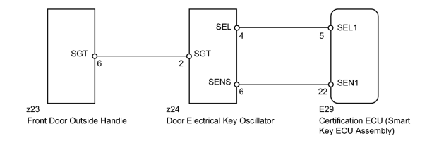
If the driver side door entry unlock function does not operate but the entry lock function operates, the communication line between the vehicle and electrical key transmitter is normal. The part at fault may be a touch sensor circuit (certification ECU [smart key ECU assembly] → driver side door outside handle → driver side door electrical key oscillator).
WIRING DIAGRAM
INSPECTION PROCEDURE
PROCEDURE
|
1. |
CHECK POWER DOOR LOCK OPERATION |
(a) When the master switch assembly door control switch is operated, check that the locked doors unlock.
OK:
Door locks operate normally.
|

|
2. |
READ VALUE USING TECHSTREAM (TOUCH SENSOR) |
(a) Using the Techstream, read the Data List.
Smart Access
|
Tester Display |
Measurement Item/Range |
Normal Condition |
Diagnostic Note |
|---|---|---|---|
|
D-Door Touch Sensor |
Driver side door touch sensor / ON or OFF |
ON: Touch sensor touched OFF: Touch sensor not touched |
- |
OK:
"ON" (sensor is touched) and "OFF" (sensor is not touched) appears on the screen.
|
|
3. |
CHECK HARNESS AND CONNECTOR (CERTIFICATION ECU [SMART KEY ECU ASSEMBLY] - DOOR ELECTRICAL KEY OSCILLATOR) |
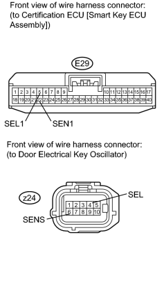
|
(a) Disconnect the E29 ECU connector. |
(b) Disconnect the z24 oscillator connector.
(c) Measure the resistance according to the value(s) in the table below.
Standard Resistance:
|
Tester Connection |
Condition |
Specified Condition |
|---|---|---|
|
E29-5 (SEL1) - z24-4 (SEL) |
Always |
Below 1 Ω |
|
E29-22 (SEN1) - z24-6 (SENS) |
Always |
Below 1 Ω |
|
E29-5 (SEL1) - Body ground |
Always |
10 kΩ or higher |
|
E29-22 (SEN1) - Body ground |
Always |
10 kΩ or higher |
|
|
4. |
CHECK HARNESS AND CONNECTOR (DOOR ELECTRICAL KEY OSCILLATOR - FRONT DOOR OUTSIDE HANDLE) |
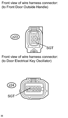
|
(a) Disconnect the z23 handle connector. |
(b) Disconnect the z24 oscillator connector.
(c) Measure the resistance according to the value(s) in the table below.
Standard Resistance:
|
Tester Connection |
Condition |
Specified Condition |
|---|---|---|
|
z23-6 (SGT) - z24-2 (SGT) |
Always |
Below 1 Ω |
|
z23-6 (SGT) - Body ground |
Always |
10 kΩ or higher |
|
|
5. |
REPLACE DOOR ELECTRICAL KEY OSCILLATOR |
(a) Replace the door electrical key oscillator
 .
.
|
|
6. |
CHECK DOOR ELECTRICAL KEY OSCILLATOR OPERATION |
(a) Check that the entry function operates normally.
OK:
Operates normally.
|
|
7. |
REPLACE FRONT DOOR OUTSIDE HANDLE |
(a) Replace the front door outside handle
.
|
|
8. |
CHECK FRONT DOOR OUTSIDE HANDLE OPERATION |
(a) Check that the entry function operates normally.
OK:
Operates normally.
|

|

|