| Last Modified: 11-27-2007 | 1.6 J | |
| Service Category: Vehicle Interior | Section: Meter/Gauge/Display | |
| Model Year: 2008 | Model: LX570 | Doc ID: RM000002ZMA005X |
| Title: METER / GAUGE / DISPLAY: METER / GAUGE SYSTEM: DESCRIPTION (2008 LX570) | ||
|
Operating Light Control Rheostat does not Change Light Brightness |
DESCRIPTION
When the light control rheostat knob is turned to the left, the combination meter and vehicle interior illumination will dim. When the light control rheostat knob is turned to the right, the combination meter and vehicle illumination will become brighter.
WIRING DIAGRAM
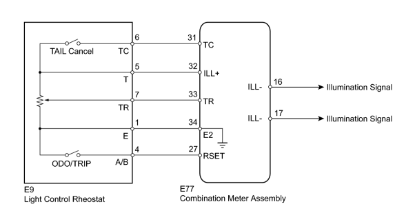
INSPECTION PROCEDURE
PROCEDURE
|
1. |
READ VALUE USING TECHSTREAM (LIGHT CONTROL RHEOSTAT) |
(a) Operate the Techstream according to the display and select the Data List
 .
.
Combination Meter
|
Tester Display |
Measurement Item/Range |
Normal Condition |
Diagnostic Note |
|---|---|---|---|
|
Tail Cancel SW |
TAIL cancel switch condition/ON or OFF |
ON: TAIL cancel switch on OFF: TAIL cancel switch off |
- |
|
Rheostat value |
Light control rheostat switch input/Min.: 0, Max.: 100 |
Light control rheostat switch is fully turned left (0) → fully turned right (100) |
Unit: % |
OK:
Light brightness can be changed within specified range by manual operation.
|

|
2. |
INSPECT LIGHT CONTROL RHEOSTAT |
(a) Inspect the light control rheostat.
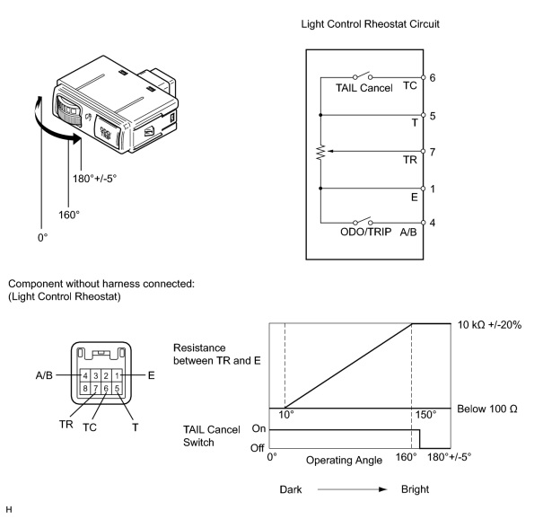
(1) Remove the light control rheostat
.
(2) Measure the resistance according to the table below.
Standard Resistance:
|
Tester Connection |
Switch Condition |
Specified Condition |
|---|---|---|
|
6 (TC) - 5 (T) |
TAIL cancel switch off → on |
10 kΩ or higher → Below 1 Ω |
|
5 (T) - 1 (E) |
Always |
10 kΩ +/- 20% |
|
7 (TR) - 1 (E) |
Light control rheostat fully turned left → fully turned right |
10 kΩ +/- 20% → Below 100 Ω |
(b) Inspect the ODO/TRIP switch.
(1) Measure the resistance according to the table below.
Standard Resistance:
|
Tester Connection |
Switch Condition |
Specified Condition |
|---|---|---|
|
4 (A/B) - 1 (E) |
ODO/TRIP switch on (Pushed) |
Below 100 Ω |
|
ODO/TRIP switch off (Not pushed) |
1 MΩ or higher |
|
|
3. |
CHECK HARNESS AND CONNECTOR (COMBINATION METER - LIGHT CONTROL RHEOSTAT) |
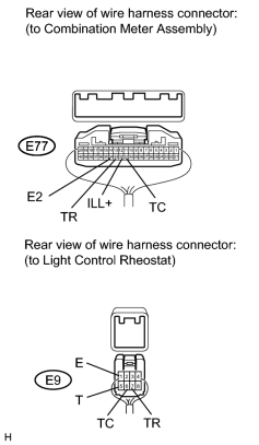
(a) Disconnect the E77 meter connector.
(b) Disconnect the E9 rheostat connector.
(c) Measure the resistance according to the value(s) in the table below.
Standard Resistance:
|
Tester Connection |
Condition |
Specified Condition |
|---|---|---|
|
E77-32 (ILL+) - E9-5 (T) |
Always |
Below 1 Ω |
|
E77-33 (TR) - E9-7 (TR) |
||
|
E77-34 (E2) - E9-1 (E) |
||
|
E7-31 (TC) - E9-6 (TC) |
|
|
4. |
REPLACE COMBINATION METER ASSEMBLY |
(a) Replace the combination meter assembly with a new or normally operating one. Perform an operation inspection.
OK:
Combination meter assembly operates normally.
|

|

|