| Last Modified: 11-27-2007 | 1.6 J | |
| Service Category: Vehicle Interior | Section: Meter/Gauge/Display | |
| Model Year: 2008 | Model: LX570 | Doc ID: RM000002ZMC005X |
| Title: METER / GAUGE / DISPLAY: METER / GAUGE SYSTEM: DESCRIPTION (2008 LX570) | ||
|
Meter Illumination does not Dim at Night |
DESCRIPTION
If the dimmer switch is turned to tail, head or AUTO, the main body ECU sends a TAIL relay signal, panel light illumination signal, panel relay signal, and TAIL cancel OFF signal to the combination meter. Then the meter and accessory meter become dim.
HINT:
TAIL cancel switch: When the headlights are illuminated and the TAIL cancel switch is turned off, the meter does not dim.
WIRING DIAGRAM
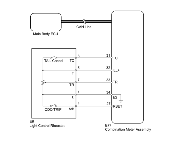
INSPECTION PROCEDURE
PROCEDURE
|
1. |
CHECK CAN COMMUNICATION SYSTEM |
(a) Check for DTCs
 .
.
Result
|
Result |
Proceed to |
|---|---|
|
CAN communication system DTC is not output |
A |
|
CAN communication system DTC is output |
B |
|

|
2. |
READ VALUE USING TECHSTREAM (LIGHT CONTROL RHEOSTAT) |
(a) Operate the Techstream according to the display and select the Data List
.
Combination Meter
|
Tester Display |
Measurement Item/Range |
Normal Condition |
Diagnostic Note |
|---|---|---|---|
|
Tail Cancel SW |
TAIL cancel switch condition/ON or OFF |
ON: TAIL cancel switch on OFF: TAIL cancel switch off |
- |
|
Rheostat value |
Light control rheostat switch input/Min.: 0, Max.: 100 |
Light control rheostat switch is fully turned left (0) → fully turned right (100) |
Unit: % |
OK:
Light brightness can be changed within specified range by manual operation.
|
|
3. |
INSPECT LIGHT CONTROL RHEOSTAT |
(a) Inspect the light control rheostat.
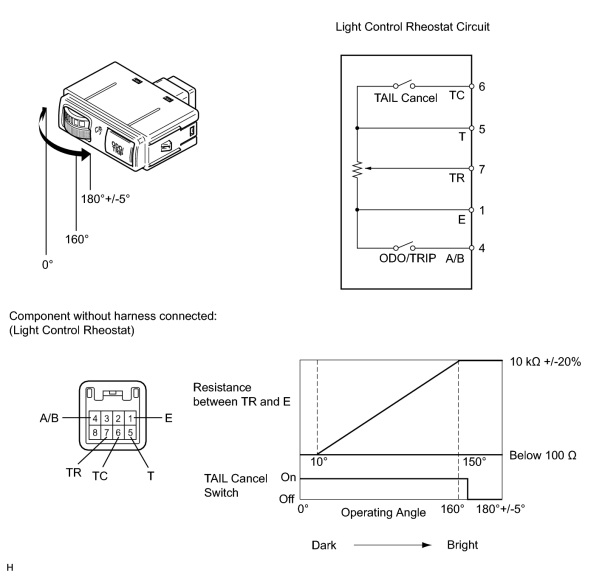
(1) Remove the light control rheostat
.
(2) Measure the resistance according to the value(s) in the table below.
Standard Resistance:
|
Tester Connection |
Switch Condition |
Specified Condition |
|---|---|---|
|
6 (TC) - 5 (T) |
TAIL cancel switch off → on |
10 kΩ or higher → Below 1 Ω |
|
5 (T) - 1 (E) |
Always |
10 kΩ +/-20% |
|
7 (TR) - 1 (E) |
Light control rheostat fully turned right → fully turned left |
10 kΩ +/-20% → Below 100 Ω |
(b) Inspect the ODO/TRIP switch.
(1) Measure the resistance according to the value(s) in the table below.
Standard Resistance:
|
Tester Connection |
Switch Condition |
Specified Condition |
|---|---|---|
|
4 (A/B) - 1 (E) |
ODO/TRIP switch on (Pushed) |
Below 100 Ω |
|
ODO/TRIP switch off (Not pushed) |
1 MΩ or higher |
|
|
4. |
CHECK HARNESS AND CONNECTOR (COMBINATION METER - LIGHT CONTROL RHEOSTAT) |
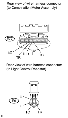
|
(a) Disconnect the E77 meter connector. |
(b) Disconnect the E9 rheostat connector.
(c) Measure the resistance according to the value(s) in the table below.
Standard Resistance:
|
Tester Connection |
Condition |
Specified Condition |
|---|---|---|
|
E77-32 (ILL+) - E9-5 (T) |
Always |
Below 1 Ω |
|
E77-33 (TR) - E9-7 (TR) |
||
|
E77-34 (E2) - E9-1 (E) |
||
|
E77-31 (TC) - E9-6 (TC) |
|

|

|