| Last Modified: 11-27-2007 | 1.6 J | |
| Service Category: Vehicle Interior | Section: Meter/Gauge/Display | |
| Model Year: 2008 | Model: LX570 | Doc ID: RM000002ZNF005X |
| Title: METER / GAUGE / DISPLAY: METER / GAUGE SYSTEM: DESCRIPTION (2008 LX570) | ||
|
Voltage Meter Malfunction |
DESCRIPTION
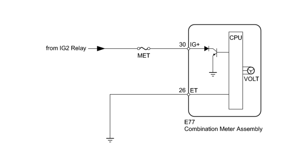
The voltmeter indicates the voltage applied to the IG+ terminal of the combination meter.
WIRING DIAGRAM
INSPECTION PROCEDURE
PROCEDURE
|
1. |
INSPECT FUSE (MET) |
(a) Remove the MET fuse from the engine room relay block.
(b) Measure the resistance according to the value(s) in the table below.
Standard Resistance:
|
Tester Connection |
Condition |
Specified Condition |
|---|---|---|
|
MET fuse |
Always |
Below 1 Ω |
|

|
2. |
PERFORM ACTIVE TEST USING TECHSTREAM (VOLTMETER) |
(a) Operate the Techstream according to the display and select the Active Test
 .
.
Combination Meter
|
Tester Display |
Test Part |
Control Range |
Diagnostic Note |
|---|---|---|---|
|
Volt meter Operation |
Voltmeter |
0, 3, 6, 9, 12, 15, or 18 |
Perform the test with the vehicle stopped and the engine idling. |
OK:
Needle indication is normal.
|
|
3. |
CHECK HARNESS AND CONNECTOR (COMBINATION METER - BATTERY AND BODY GROUND) |
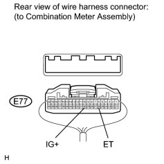
(a) Disconnect the E77 meter connector.
(b) Measure the resistance and voltage according to the value(s) in the tables below.
Standard Resistance:
|
Tester Connection |
Condition |
Specified Condition |
|---|---|---|
|
E77-26 (ET) - Body ground |
Always |
Below 1 Ω |
Standard Voltage:
|
Tester Connection |
Switch Condition |
Specified Condition |
|---|---|---|
|
E77-30 (IG+) - Body ground |
Engine switch on (IG) |
11 to 14 V |
|
Engine switch off |
Below 1 V |
|

|

|