| Last Modified: 11-27-2007 | 1.6 J | |
| Service Category: Vehicle Interior | Section: Meter/Gauge/Display | |
| Model Year: 2008 | Model: LX570 | Doc ID: RM0000030W5005X |
| Title: METER / GAUGE / DISPLAY: METER / GAUGE SYSTEM: DESCRIPTION (2008 LX570) | ||
|
Fuel Receiver Gauge Malfunction |
DESCRIPTION
The fuel sender gauge has a variable resistance mechanism. The resistance decreases when the fuel amount increases, and the resistance increases when the fuel amount decreases. The fuel receiver gauge changes based on the resistance of the fuel sender gauge.
WIRING DIAGRAM
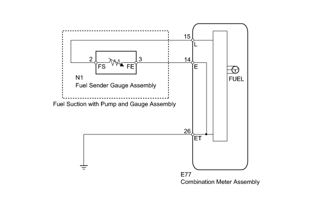
INSPECTION PROCEDURE
PROCEDURE
|
1. |
CHECK FOR DTC |
(a) Check for DTCs
 .
.
Result
|
Result |
Proceed to |
|---|---|
|
DTC B1500 is not output |
A |
|
DTC B1500 is output |
B |
|

|
2. |
CHECK HARNESS AND CONNECTOR (COMBINATION METER - FUEL RECEIVER GAUGE AND BODY GROUND) |
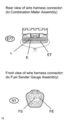
(a) Disconnect the E77 meter connector.
(b) Disconnect the N1 gauge connector.
(c) Measure the resistance according to the value(s) in the table below.
Standard Resistance:
|
Tester Connection |
Condition |
Specified Condition |
|---|---|---|
|
E77-15 (L) - N1-2 (FS) |
Always |
Below 1 Ω |
|
E77-14 (E) - N1-3 (FE) |
||
|
E77-26 (ET) - Body ground |
||
|
E77-15 (L) or N1-2 (FS) - Body ground |
Always |
10 kΩ or higher |
|
|
3. |
INSPECT FUEL SUCTION WITH PUMP AND GAUGE ASSEMBLY |
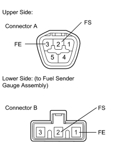
(a) Remove the fuel sender gauge
.
(b) Measure the resistance according to the value(s) in the table below.
Standard Resistance:
|
Tester Connection |
Condition |
Specified Condition |
|---|---|---|
|
A-2 (FS) - B-2 (FS) |
Always |
Below 1 Ω |
|
A-3 (FE) - B-1 (FE) |
|
|
4. |
INSPECT FUEL SENDER GAUGE ASSEMBLY |
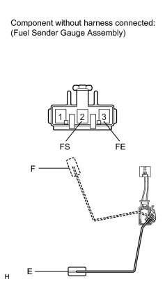
(a) Remove the fuel sender gauge
.
(b) Measure the resistance according to the value(s) in the table below.
Standard Resistance:
|
Tester Connection |
Condition |
Specified Condition |
|---|---|---|
|
2 (FS) - 3 (FE) |
Float level is F (upper) |
12 to 18 Ω |
|
Float level is E (lower) |
405 to 415 Ω |
|

|

|