| Last Modified: 11-27-2007 | 1.6 G | |
| Service Category: Engine/Hybrid System | Section: Intake/Exhaust | |
| Model Year: 2008 | Model: LX570 | Doc ID: RM0000031GR005X |
| Title: 3UR-FE INTAKE / EXHAUST: VACUUM SWITCHING VALVE (for ACIS): ON-VEHICLE INSPECTION (2008 LX570) | ||
ON-VEHICLE INSPECTION
1. REMOVE V-BANK COVER SUB-ASSEMBLY

2. INSPECT VACUUM SWITCHING VALVE ASSEMBLY (for ACIS)
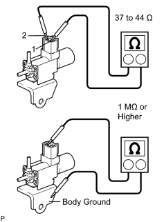
(a) Disconnect the vacuum switching valve connector.
|
(b) Measure the resistance according to the value(s) in the table below. Standard Resistance:
If the result is not as specified, replace the vacuum switching valve assembly. |
|
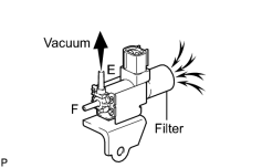
(c) When applying vacuum to port E, check that air is sucked into the filter. If the result is not as specified, replace the vacuum switching valve assembly. |
|
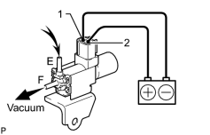
(d) Apply battery voltage to the connector, and check the VSV operation. OK:
If the result is not as specified, replace the vacuum switching valve assembly. |
(e) Connect the vacuum switching valve connector.
3. INSTALL V-BANK COVER SUB-ASSEMBLY

|

|