| Last Modified: 11-27-2007 | 1.6 A | |
| Service Category: Engine/Hybrid System | Section: Engine Mechanical | |
| Model Year: 2008 | Model: LX570 | Doc ID: RM0000031RQ004X |
| Title: 3UR-FE ENGINE MECHANICAL: ENGINE ASSEMBLY: INSTALLATION (2008 LX570) | ||
INSTALLATION
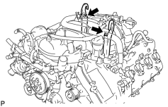
1. REMOVE ENGINE STAND
|
(a) Install 2 engine hangers with 2 bolts as shown in the illustration. Part No.:
Torque: 43 N·m (438 kgf·cm, 32 ft·lbf) |
(b) Attach an engine sling device and hang the engine with a chain block.
(c) Remove the bolts and engine assembly from the engine stand.
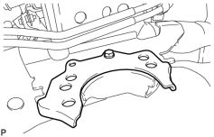
2. INSTALL FRONT NO. 2 ENGINE MOUNTING BRACKET LH
|
(a) Install the engine mounting bracket LH with the bolt. Torque: 32 N·m (326 kgf·cm, 24 ft·lbf) |
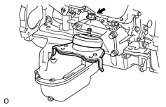
3. INSTALL FRONT ENGINE MOUNTING INSULATOR RH
|
(a) Install the mounting insulator with the nut. Torque: 72 N·m (734 kgf·cm, 53 ft·lbf) |
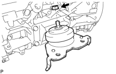
4. INSTALL FRONT ENGINE MOUNTING INSULATOR LH
|
(a) Install the mounting insulator with the nut. Torque: 72 N·m (734 kgf·cm, 53 ft·lbf) |
5. INSTALL ENGINE ASSEMBLY
(a) Slowly lower the engine assembly into the engine compartment.
NOTICE:
Make sure that the engine is clear of all wiring and hoses.
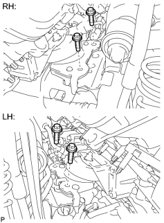
(b) Attach the engine mounting insulators to the vehicle.
|
(c) Install the 4 engine mounting insulator bolts. Torque: 79 N·m (806 kgf·cm, 58 ft·lbf) |
(d) Remove the 2 bolts and 2 engine hangers.
6. INSTALL NO. 2 WATER BY-PASS PIPE
|
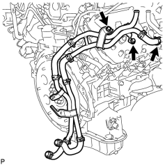
(a) Connect the hose and install the water by-pass pipe with the 2 bolts. Torque: 18 N·m (184 kgf·cm, 13 ft·lbf) |
7. CONNECT OIL COOLER PIPE ASSEMBLY

8. INSTALL DRIVE PLATE AND RING GEAR SUB-ASSEMBLY
|
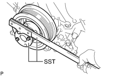
(a) Using SST, hold the crankshaft. SST: 09213-70011 09213-70020 SST: 09330-00021 |
(b) Install the crankshaft angle sensor rotor, drive plate and rear drive plate spacer to the crankshaft.
|
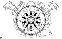
(c) Install and uniformly tighten 10 new bolts in the sequence shown in the illustration. Torque: 30 N·m (301 kgf·cm, 22 ft·lbf) NOTICE:
|
|
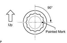
(d) Mark the upside of each flywheel installation bolt with paint. |
(e) Tighten the flywheel installation bolts 90° as shown in the illustration.
(f) Check that the painted marks are now at a 90° angle to the upside.
9. INSTALL REAR NO. 1 ENGINE MOUNTING INSULATOR
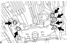
(a) Install the rear engine mounting insulator to the transmission with the 4 bolts.
Torque: 59 N·m (602 kgf·cm, 44 ft·lbf)
(b) Install the engine mounting heat insulator with the 2 bolts.
Torque: 12 N·m (122 kgf·cm, 9 ft·lbf)
10. INSTALL AUTOMATIC TRANSMISSION ASSEMBLY
(a) Install the automatic transmission
.
11. INSTALL STARTER ASSEMBLY
12. INSTALL STARTER COVER
13. INSTALL EXHAUST MANIFOLD SUB-ASSEMBLY RH
14. INSTALL NO. 1 EXHAUST MANIFOLD HEAT INSULATOR
15. INSTALL NO. 1 MANIFOLD STAY
16. INSTALL EXHAUST MANIFOLD SUB-ASSEMBLY LH
17. INSTALL NO. 2 EXHAUST MANIFOLD HEAT INSULATOR
18. INSTALL NO. 2 MANIFOLD STAY
19. INSTALL PROPELLER SHAFT HEAT INSULATOR
20. INSTALL REAR PROPELLER SHAFT ASSEMBLY
(a) Install the rear propeller shaft
.
21. INSTALL FRONT PROPELLER SHAFT ASSEMBLY
(a) Install the front propeller shaft
.
22. INSTALL FRONT EXHAUST PIPE ASSEMBLY
23. INSTALL FRONT NO. 2 EXHAUST PIPE ASSEMBLY
24. INSTALL CENTER EXHAUST PIPE ASSEMBLY
25. INSTALL TAILPIPE ASSEMBLY
26. INSTALL ENGINE OIL LEVEL DIPSTICK GUIDE
27. INSTALL GENERATOR ASSEMBLY
28. CONNECT VANE PUMP ASSEMBLY
29. CONNECT COOLER COMPRESSOR ASSEMBLY
30. CONNECT WIRE HARNESS AND HOSE
|
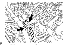
(a) Connect the 2 clamps and 2 connectors. |
|
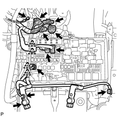
(b) Connect the 2 connectors and 2 clips to the engine room junction block. |
(c) Install the engine wire with the nut. Then connect the 2 clips.
Torque: 10 N·m (102 kgf·cm, 7 ft·lbf)
(d) Connect the 4 air injection control driver connectors.
(e) Install the ground wire to the air injection control bracket with the bolt.
Torque: 8.0 N·m (82 kgf·cm, 71 in·lbf)
(f) Install the ground wire to the body with the bolt.
Torque: 8.4 N·m (86 kgf·cm, 74 in·lbf)
(g) Connect the cable to the positive (+) battery terminal.
(h) Install the wire to the positive (+) battery cable with the nut.
Torque: 5.4 N·m (55 kgf·cm, 48 in·lbf)
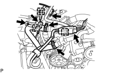
|
(i) Connect the 2 air injection system hoses. |
(j) Install the ground wire with the bolt.
Torque: 8.0 N·m (82 kgf·cm, 71 in·lbf)
(k) Connect the 3 clamps and 2 air pump connectors.
(l) Install the connector bracket with the nut.
Torque: 8.0 N·m (82 kgf·cm, 71 in·lbf)
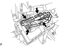
|
(m) Connect the clamp and 4 connectors to the connector holder block. |
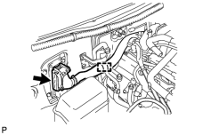
|
(n) Connect the ECM connector and clamp. HINT:
Refer to the following procedures to connect the ECM connector
|
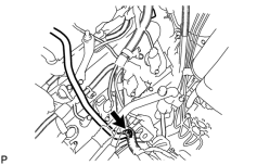
|
(o) Connect the purge line hose. |
31. CONNECT FUEL MAIN AND RETURN HOSE
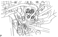
|
(a) Connect the fuel main and return hoses
|
(b) Install the fuel pipe clamp.
32. INSTALL WATER HOSE SUB-ASSEMBLY
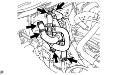
33. INSTALL RADIATOR ASSEMBLY
34. INSTALL FAN SHROUD
35. INSTALL NO. 2 RADIATOR HOSE
36. INSTALL NO. 1 RADIATOR HOSE
37. INSTALL AIR CLEANER ASSEMBLY
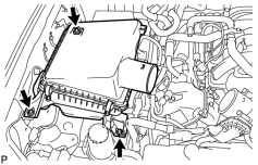
|
(a) Install the air cleaner with the 3 bolts. Torque: 5.0 N·m (51 kgf·cm, 44 in·lbf) |
38. INSTALL AIR CLEANER HOSE ASSEMBLY
39. INSTALL HOOD SUB-ASSEMBLY
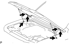
|
(a) Install the hood with the 4 bolts. Torque: 13 N·m (133 kgf·cm, 10 ft·lbf) |
(b) Connect the 2 hood supports with the 2 hood support bolts.
Torque: 18 N·m (184 kgf·cm, 13 ft·lbf)
CAUTION:
Install the hood support while supporting the hood by hand.
NOTICE:
Check that the hood support is engaged in the ball joint and that it cannot be pulled out.
40. ADJUST HOOD SUB-ASSEMBLY
41. INSTALL COWL TOP VENTILATOR LOUVER SUB-ASSEMBLY
42. INSTALL HOOD TO COWL TOP SEAL
43. INSTALL FRONT FENDER MAIN SEAL LH
44. INSTALL FRONT FENDER MAIN SEAL RH
45. INSTALL FRONT WIPER ARM LH
46. INSTALL FRONT WIPER ARM RH
47. INSTALL RADIATOR SIDE DEFLECTOR RH (w/o Air Cooled Transmission Oil Cooler)
48. INSTALL RADIATOR SIDE DEFLECTOR LH
49. INSTALL RADIATOR GRILLE
50. INSTALL FRONT FENDER APRON SEAL REAR RH
51. INSTALL FRONT FENDER APRON SEAL FRONT RH
52. INSTALL FRONT FENDER APRON SEAL REAR LH
53. INSTALL FRONT FENDER APRON SEAL FRONT LH
54. INSTALL OIL PAN PROTECTOR ASSEMBLY
55. INSTALL NO. 2 ENGINE UNDER COVER
56. INSTALL NO. 1 ENGINE UNDER COVER SUB-ASSEMBLY
57. INSTALL FRONT FENDER SPLASH SHIELD SUB-ASSEMBLY LH
58. INSTALL FRONT FENDER SPLASH SHIELD SUB-ASSEMBLY RH
59. ADD ENGINE OIL
60. ADD ENGINE COOLANT
61. CONNECT CABLE TO NEGATIVE BATTERY TERMINAL
NOTICE:
When disconnecting the cable, some systems need to be initialized after the cable is reconnected
.
62. INSPECT FOR OIL LEAK
63. INSPECT FOR COOLANT LEAK
64. INSPECT FOR EXHAUST GAS LEAK
65. INSPECT FOR FUEL LEAK
66. INSPECT SHIFT LEVER POSITION
67. INSPECT IGNITION TIMING
68. INSPECT ENGINE IDLE SPEED
69. INSPECT CO/HC
70. INSPECT ENGINE OIL LEVEL
71. INSPECT ENGINE COOLANT LEVEL
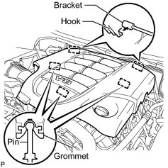
72. INSTALL V-BANK COVER SUB-ASSEMBLY
|
(a) Attach the 2 V-bank cover hooks to the bracket. Then align the 3 V-bank cover grommets with the 3 pins, and press down on the V-bank cover to attach the pins. |
73. INSTALL UPPER RADIATOR SUPPORT SEAL
74. INSTALL ENGINE ROOM SIDE COVER RH
75. INSTALL ENGINE ROOM SIDE COVER LH

|

|