| Last Modified: 11-27-2007 | 1.6 J | |
| Service Category: Engine/Hybrid System | Section: Engine Control | |
| Model Year: 2008 | Model: LX570 | Doc ID: RM000003302008X |
| Title: 3UR-FE ENGINE CONTROL: SFI SYSTEM: DESCRIPTION (2008 LX570) | ||
|
Fuel Injector Circuit |
DESCRIPTION
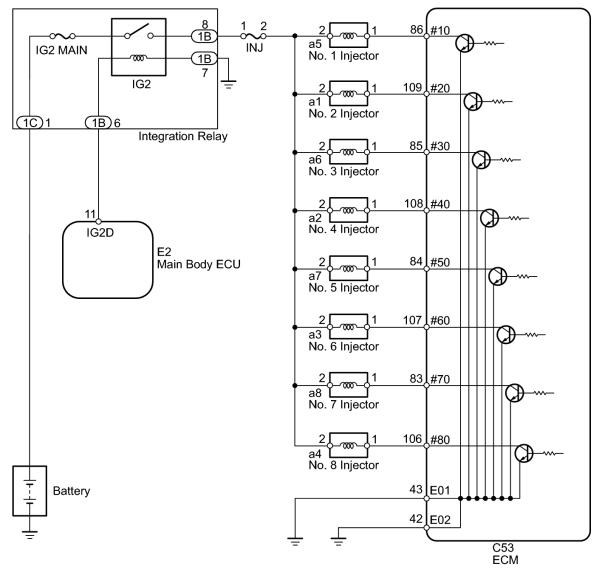
The fuel injectors are located on the intake manifold. They inject fuel into the cylinders based on the signals from the ECM.
WIRING DIAGRAM
INSPECTION PROCEDURE
PROCEDURE
|
1. |
CHECK INJECTOR ASSEMBLY (POWER SOURCE) |
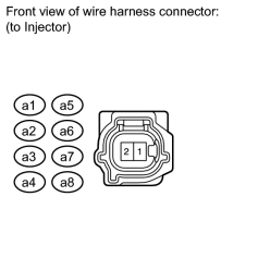
(a) Disconnect the fuel injector connector.
(b) Turn the engine switch on (IG).
(c) Measure the voltage according to the value(s) in the table below.
Standard Voltage:
|
Cylinder |
Tester Connection |
Switch Condition |
Specified Condition |
|---|---|---|---|
|
No. 1 |
a5-2 - Ground |
Engine switch on (IG) |
11 to 14 V |
|
No. 2 |
a1-2 - Ground |
Engine switch on (IG) |
11 to 14 V |
|
No. 3 |
a6-2 - Ground |
Engine switch on (IG) |
11 to 14 V |
|
No. 4 |
a2-2 - Ground |
Engine switch on (IG) |
11 to 14 V |
|
No. 5 |
a7-2 - Ground |
Engine switch on (IG) |
11 to 14 V |
|
No. 6 |
a3-2 - Ground |
Engine switch on (IG) |
11 to 14 V |
|
No. 7 |
a8-2 - Ground |
Engine switch on (IG) |
11 to 14 V |
|
No. 8 |
a4-2 - Ground |
Engine switch on (IG) |
11 to 14 V |
|

|
2. |
INSPECT FUEL INJECTOR ASSEMBLY |
(a) Inspect the fuel injector
 .
.
|
|
3. |
CHECK HARNESS AND CONNECTOR (FUEL INJECTOR ASSEMBLY - ECM) |
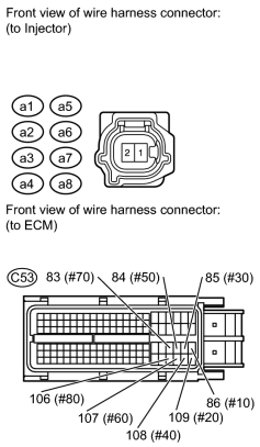
(a) Disconnect the fuel injector connector.
(b) Disconnect the C53 ECM connector.
(c) Measure the resistance according to the value(s) in the table below.
Standard Resistance:
|
Cylinder |
Tester Connection |
Condition |
Specified Condition |
|---|---|---|---|
|
No. 1 |
a5-1 - Body ground |
Always |
10 kΩ or higher |
|
a5-1 - C53-86 (#10) |
Always |
Below 1 Ω |
|
|
No. 2 |
a1-1 - Body ground |
Always |
10 kΩ or higher |
|
a1-1 - C53-109 (#20) |
Always |
Below 1 Ω |
|
|
No. 3 |
a6-1 - Body ground |
Always |
10 kΩ or higher |
|
a6-1 - C53-85 (#30) |
Always |
Below 1 Ω |
|
|
No. 4 |
a2-1 - Body ground |
Always |
10 kΩ or higher |
|
a2-1 - C53-108 (#40) |
Always |
Below 1 Ω |
|
|
No. 5 |
a7-1 - Body ground |
Always |
10 kΩ or higher |
|
a7-1 - C53-84 (#50) |
Always |
Below 1 Ω |
|
|
No. 6 |
a3-1 - Body ground |
Always |
10 kΩ or higher |
|
a3-1 - C53-107 (#60) |
Always |
Below 1 Ω |
|
|
No. 7 |
a8-1 - Body ground |
Always |
10 kΩ or higher |
|
a8-1 - C53-83 (#70) |
Always |
Below 1 Ω |
|
|
No. 8 |
a4-1 - Body ground |
Always |
10 kΩ or higher |
|
a4-1 - C53-106 (#80) |
Always |
Below 1 Ω |
|
|
4. |
INSPECT FUSE (INJ, IG2 MAIN) |
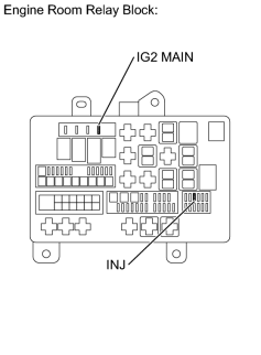
(a) Remove the INJ fuse and IG2 MAIN fuse from the engine room relay block.
(b) Measure the resistance according to the value(s) in the table below.
Standard Resistance:
|
Tester Connection |
Condition |
Specified Condition |
|---|---|---|
|
INJ fuse |
Always |
Below 1 Ω |
|
IG2 MAIN fuse |
Always |
Below 1 Ω |
|
|
5. |
INSPECT INTEGRATION RELAY (IG2) |
(a) Inspect the integration relay
.
|

|

|