- Harness or connector between No. 2 air conditioning harness assembly and air conditioning amplifier assembly
- No. 2 air conditioning harness assembly (rear evaporator temperature sensor)
- Air conditioning amplifier assembly
| Last Modified: 11-27-2007 | 1.6 C | |
| Service Category: Vehicle Interior | Section: Heating/Air Conditioning | |
| Model Year: 2008 | Model: LX570 | Doc ID: RM0000033J8006X |
| Title: HEATING / AIR CONDITIONING: AIR CONDITIONING SYSTEM: DESCRIPTION (2008 LX570) | ||
|
DTC |
B1417/17 |
Rear Evaporator Temperature Sensor Circuit |
DESCRIPTION
The rear evaporator temperature sensor is installed on the evaporator in the rear air conditioning unit to detect the cooled air temperature that has passed through the evaporator and control the air conditioning. It sends appropriate signals to the air conditioning amplifier assembly. The resistance of the rear evaporator temperature sensor changes in accordance with the cooled air temperature that has passed through the rear evaporator. As the temperature decreases, the resistance increases. As the temperature increases, the resistance decreases.
The air conditioning amplifier assembly applies voltage (5 V) to the rear evaporator temperature sensor and reads voltage changes as the resistance of the rear evaporator temperature sensor changes. This sensor is used for frost prevention.
|
DTC Code |
DTC Detection Condition |
Trouble Area |
|---|---|---|
|
B1417/17 |
An open or short in the rear evaporator temperature sensor circuit. |
|
WIRING DIAGRAM
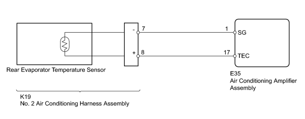
INSPECTION PROCEDURE
PROCEDURE
|
1. |
READ VALUE USING TECHSTREAM (REAR EVAPORATOR TEMPERATURE SENSOR) |
(a) Use the Data List to check if the rear evaporator temperature sensor is functioning properly.
Air Conditioner
|
Tester Display |
Measurement Item/Range |
Normal Condition |
Diagnostic Note |
|---|---|---|---|
|
Ambient Temp Sens (Rear) |
Rear evaporator temperature sensor / Min.: -29.7°C (-21.46°F) Max.: 59.55°C (139.19°F) |
Actual rear evaporator temperature displayed |
Open in the circuit: -73°C (-99.4°F). Short in the circuit: 114°C (237.2°F). |
OK:
The display is as specified in the normal condition.
|

|
2. |
INSPECT REAR EVAPORATOR TEMPERATURE SENSOR |
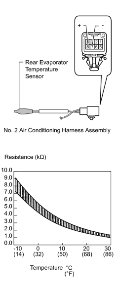
(a) Remove the No. 2 air conditioning harness assembly
 .
.
(b) Measure the resistance according to the value(s) in the table below.
Standard Resistance:
|
Tester Connection |
Condition |
Specified Condition |
|---|---|---|
|
7 (-) - 8 (+) |
-10°C (14°F) |
7.30 to 9.10 kΩ |
|
-5°C (23°F) |
5.65 to 6.95 kΩ |
|
|
0°C (32°F) |
4.40 to 5.35 kΩ |
|
|
5°C (41°F) |
3.40 to 4.15 kΩ |
|
|
10°C (50°F) |
2.70 to 3.25 kΩ |
|
|
15°C (59°F) |
2.14 to 2.58 kΩ |
|
|
20°C (68°F) |
1.71 to 2.05 kΩ |
|
|
25°C (77°F) |
1.38 to 1.64 kΩ |
|
|
30°C (86°F) |
1.11 to 1.32 kΩ |
NOTICE:
- Even slightly touching the sensor may change the resistance value. Be sure to hold the connector of the sensor.
- When measuring, the sensor temperature must be the same as the ambient temperature.
HINT:
As the temperature increases, the resistance decreases (See the graph).
|
|
3. |
CHECK HARNESS AND CONNECTOR (NO. 2 AIR CONDITIONING HARNESS - AIR CONDITIONING AMPLIFIER) |
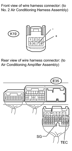
(a) Disconnect the K19 No. 2 air conditioning harness assembly connector.
(b) Disconnect the E35 amplifier connector.
(c) Measure the resistance according to the value(s) in the table below.
Standard Resistance:
|
Tester Connection |
Condition |
Specified Condition |
|---|---|---|
|
K19-8 (+) - E35-17 (TEC) |
Always |
Below 1 Ω |
|
K19-7 (-) - E35-1 (SG) |
Always |
Below 1 Ω |
|
E35-17 (TEC) - Body ground |
Always |
0.3 to 27 kΩ |
|
E35-1 (SG) - Body ground |
Always |
Below 1 Ω |
|
|
4. |
CHECK NO. 2 AIR CONDITIONING HARNESS ASSEMBLY (OPERATION) |
(a) Replace the No. 2 air conditioning harness assembly with a normal one and check that the condition returns to normal
.
|
|
5. |
CHECK FOR DTC |
(a) Clear the DTCs
.
(b) Check for DTCs
.
OK:
DTC B1417 is not output.
|

|

|