| Last Modified: 11-27-2007 | 1.6 J | |
| Service Category: Audio/Visual/Telematics | Section: Park Assist/Monitoring | |
| Model Year: 2008 | Model: LX570 | Doc ID: RM0000035BD002X |
| Title: PARK ASSIST / MONITORING: INTUITIVE PARKING ASSIST SYSTEM: DESCRIPTION (2008 LX570) | ||
|
Clearance Sonar Main Switch Circuit |
DESCRIPTION
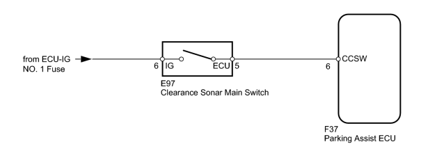
When the clearance sonar main switch turns on, the ON signal is input into the parking assist ECU.
WIRING DIAGRAM
INSPECTION PROCEDURE
PROCEDURE
|
1. |
READ VALUE USING TECHSTREAM (CLEARANCE SONAR MAIN SWITCH) |
(a) Check the Data List for proper functioning of the clearance sonar main switch.
Intuitive P/A
|
Tester Display |
Measurement Item/Range |
Normal Condition |
Diagnostic Note |
|---|---|---|---|
|
Main Switch |
Clearance sonar main switch/OFF or ON |
OFF: Clearance sonar main switch off ON: Clearance sonar main switch on |
- |
OK:
Techstream display changes according to operation of clearance sonar main switch.
|

|
3. |
INSPECT CLEARANCE SONAR MAIN SWITCH |
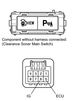
(a) Remove the clearance sonar main switch
 .
.
(b) Measure the resistance according to the value(s) in the table below.
Standard Resistance:
|
Tester Connection |
Switch Condition |
Specified Condition |
|---|---|---|
|
6 (IG) - 5 (ECU) |
Clearance sonar main switch on |
Below 1 Ω |
|
6 (IG) - 5 (ECU) |
Clearance sonar main switch off |
10 kΩ or higher |
|
|
4. |
CHECK HARNESS AND CONNECTOR (MAIN SWITCH - ECU AND BATTERY) |
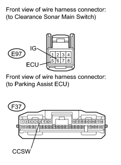
(a) Disconnect the E97 switch connector.
(b) Disconnect the F37 ECU connector.
(c) Measure the voltage according to the value(s) in the table below.
Standard Voltage:
|
Tester Connection |
Condition |
Specified Condition |
|---|---|---|
|
E97-6 (IG) - Body ground |
Engine switch on (IG) |
11 to 14 V |
|
E97-6 (IG) - Body ground |
Engine switch off |
Below 1 V |
(d) Measure the resistance according to the value(s) in the table below.
Standard Resistance:
|
Tester Connection |
Condition |
Specified Condition |
|---|---|---|
|
E97-5 (ECU) - F37-6 (CCSW) |
Always |
Below 1 Ω |
|
E97-5 (ECU) - Body ground |
Always |
10 kΩ or higher |
|

|

|