| Last Modified: 11-27-2007 | 1.6 J | |
| Service Category: Audio/Visual/Telematics | Section: Navigation/Multi Info Display | |
| Model Year: 2008 | Model: LX570 | Doc ID: RM000003A82002X |
| Title: NAVIGATION / MULTI INFO DISPLAY: NAVIGATION SYSTEM: DESCRIPTION (2008 LX570) | ||
|
Vehicle Speed Signal Circuit |
DESCRIPTION
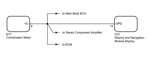
The display and navigation module display performs switch operation control during driving by receiving a vehicle speed signal from the combination meter.
HINT:
- A voltage of 12 to 15 V is output from each ECU and then input to the combination meter. The signal is changed to a pulse signal at the transistor in the combination meter. Each ECU controls its respective system based on the pulse signal.
- If a short occurs in any of the ECUs or in the wire harness connected to an ECU, all systems in the diagram below will not operate normally.
WIRING DIAGRAM
INSPECTION PROCEDURE
PROCEDURE
|
1. |
CHECK VEHICLE SPEED SIGNAL (DISPLAY CHECK MODE) |
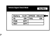
(a) Enter the "Display Check" mode and select "Vehicle Signal Check"
 .
.
|
(b) Check that the vehicle speed on the display changes according to the actual vehicle speed. OK: The display changes according to the actual vehicle speed. HINT:
This display is updated once per second. As a result, it is normal for the display to lag behind the actual change in the vehicle speed. |
|

|
2. |
CHECK COMBINATION METER (SPEEDOMETER OPERATION) |
(a) Drive the vehicle and check if the function of the speedometer in the combination meter is normal.
OK:
Actual vehicle speed and the speed indicated on the speedometer are the same.
HINT:
The vehicle speed sensor is functioning normally when the indication on the speedometer is normal.
|
|
3. |
CHECK HARNESS AND CONNECTOR (DISPLAY AND NAVIGATION MODULE DISPLAY - COMBINATION METER) |
(a) Disconnect the F23 display connector.
(b) Disconnect the E77 meter connector.
(c) Measure the resistance according to the value(s) in the table below.
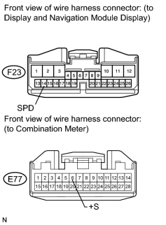
Standard Resistance:
|
Tester Connection |
Condition |
Specified Condition |
|---|---|---|
|
F23-14 (SPD) - E77-6 (+S) |
Always |
Below 1 Ω |
|
F23-14 (SPD) - Body ground |
Always |
10 kΩ or higher |
|

|

|