- Harness or connector
- Integration control and panel (Damping mode select switch)
- Suspension control ECU
| Last Modified: 11-27-2007 | 1.6 C | |
| Service Category: Suspension | Section: Suspension Control System | |
| Model Year: 2008 | Model: LX570 | Doc ID: RM000003BBK001X |
| Title: SUSPENSION CONTROL: ACTIVE HEIGHT CONTROL SUSPENSION: DESCRIPTION (2008 LX570) | ||
|
DTC |
C1791 |
Absorber Control Switch Circuit (Test Mode DTC) |
DESCRIPTION
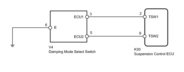
This circuit is used for sending the signal to the suspension control ECU to switch to the damping mode selected by the damping force control switch.
|
DTC Code |
Detection Condition |
Trouble Area |
|---|---|---|
|
C1791 |
The test mode procedure is performed. |
|
WIRING DIAGRAM
INSPECTION PROCEDURE
NOTICE:
- Before performing troubleshooting, inspect the connectors of related circuits.
-
If the suspension control ECU or height control sensor is replaced, the vehicle height offset calibration must be performed
 .
.
PROCEDURE
|
1. |
READ VALUE USING TECHSTREAM (SPORT SWITCH, COMFORT SWITCH) |
(a) Turn the engine switch off.
(b) Connect the Techstream to the DLC3.
(c) Turn the engine switch on (IG) and the Techstream on.
(d) Enter the following menus: Chassis / AHC / Data List.
(e) According to the display on the Techstream, read the Data List.
AHC
|
Tester Display |
Measurement Item/Range |
Normal Condition |
Diagnostic Note |
|---|---|---|---|
|
SPORT Switch |
Damping mode select switch (SPORT) / ON or OFF |
ON: SPORT OFF: NORMAL or COMFORT |
- |
|
COMFORT Switch |
Damping mode select switch (COMFORT) / ON or OFF |
ON: COMFORT OFF: NORMAL or SPORT |
- |
OK:
On the Techstream screen, item changes between ON and OFF according to switch operation.
|

|
2. |
TEST MODE INSPECTION |
(a) Refer to the Test Mode Procedure and perform the signal check. Check that test mode DTC C1791 is cleared
.
Result
|
Result |
Proceed to |
|---|---|
|
DTC C1791 is not cleared |
A |
|
DTC C1791 is cleared |
B |
|
|
3. |
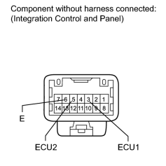
INSPECT INTEGRATION CONTROL AND PANEL (DAMPING MODE SELECT SWITCH) |
(a) Remove the integration control and panel
.
|
(b) Measure the resistance according to the value(s) in the table below. Standard Resistance:
|
|
|
4. |
CHECK HARNESS AND CONNECTOR (SUSPENSION CONTROL ECU - SWITCH AND BODY GROUND) |
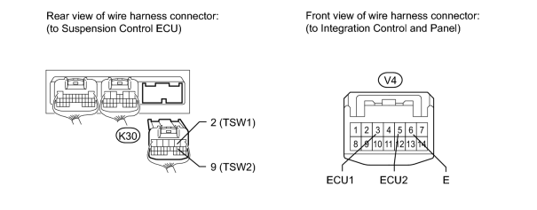
(a) Disconnect the K30 ECU connector.
(b) Disconnect the V4 integration control and panel connector.
(c) Measure the resistance according to the value(s) in the table below.
Standard Resistance:
|
Tester Connection |
Condition |
Specified Condition |
|---|---|---|
|
K30-2 (TSW1) - V4-3 (ECU1) |
Always |
Below 1 Ω |
|
K30-2 (TSW1) - Body ground |
Always |
10 kΩ or higher |
|
K30-9 (TSW2) - V4-5 (ECU2) |
Always |
Below 1 Ω |
|
K30-9 (TSW2) - Body ground |
Always |
10 kΩ or higher |
|
V4-6 (E) - Body ground |
Always |
Below 1 Ω |
|

|

|