- Lower tail gate lock RH
- Harness or connector
- No. 2 main body ECU
| Last Modified: 11-27-2007 | 1.6 C | |
| Service Category: Vehicle Exterior | Section: Door/Hatch | |
| Model Year: 2008 | Model: LX570 | Doc ID: RM000003EUM000X |
| Title: DOOR / HATCH: TAIL GATE CLOSER SYSTEM: DESCRIPTION (2008 LX570) | ||
|
DTC |
B225A |
Tail Gate Panel Position Switch RH |
DESCRIPTION
The No. 2 main body ECU receives the close position switch signal from the lower tail gate lock RH and detects the open/closed status of the lower tail gate. DTC B225A is stored when the ECU receives a close position switch malfunction signal from the lower tail gate lock RH.
|
DTC Code |
DTC Detection Condition |
Trouble Area |
|---|---|---|
|
B225A |
A close position switch malfunction (open or short circuit) signal is received from the lower tail gate lock. |
|
WIRING DIAGRAM
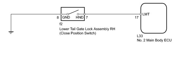
INSPECTION PROCEDURE
PROCEDURE
|
1. |
READ VALUE USING TECHSTREAM (CLOSE POSITION SWITCH) |
(a) Check the Data List for proper functioning of the close position switch.
Body No. 4
|
Tester Display |
Measurement Item/Range |
Normal Condition |
Diagnostic Note |
|---|---|---|---|
|
Position Switch RH |
Close position switch RH signal/ON or OFF |
ON: Lower tail gate closed OFF: Lower tail gate open |
- |
OK:
The display is as specified in the normal condition.
|

|
2. |
CHECK DTC OUTPUT |
(a) Starting with the lower tail gate closed, open and close the lower tail gate 6 times.
(b) Check for DTCs
 .
.
(c) Clear the DTCs
.
(d) Starting with the lower tail gate closed, open and close the lower tail gate 6 times.
(e) Recheck for DTCs
.
OK:
DTC B225A is not output.
|
|
3. |
INSPECT LOWER TAIL GATE LOCK ASSEMBLY RH |
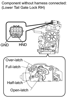
(a) Remove the lower tail gate lock RH
.
(b) Measure the resistance according to the value(s) in the table below.
Standard Resistance:
|
Tester Connection |
Condition |
Specified Condition |
|---|---|---|
|
7 (HND) - 8 (GND) |
Over-latch |
Below 1 Ω |
|
7 (HND) - 8 (GND) |
Full-latch |
10 kΩ or higher |
|
7 (HND) - 8 (GND) |
Half-latch |
10 kΩ or higher |
|
7 (HND) - 8 (GND) |
Open-latch |
10 kΩ or higher |
|
|
4. |
CHECK HARNESS AND CONNECTOR (LOCK - ECU AND BODY GROUND) |
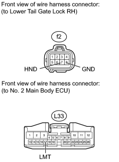
(a) Disconnect the f2 lock connector.
(b) Disconnect the L33 ECU connector.
(c) Measure the resistance according to the value(s) in the table below.
Standard Resistance:
|
Tester Connection |
Condition |
Specified Condition |
|---|---|---|
|
f2-7 (HND) - L33-17 (LMT) |
Always |
Below 1 Ω |
|
f2-8 (GND) - Body ground |
Always |
Below 1 Ω |
|
f2-7(HND) - Body ground |
Always |
10 kΩ or higher |
|

|

|