| Last Modified: 11-27-2007 | 1.6 J | |
| Service Category: Engine/Hybrid System | Section: Cruise Control | |
| Model Year: 2008 | Model: LX570 | Doc ID: RM000003FEE000X |
| Title: CRUISE CONTROL: DYNAMIC RADAR CRUISE CONTROL SYSTEM: DESCRIPTION (2008 LX570) | ||
|
Distance Control Switch Circuit |
DESCRIPTION
The distance control switch sets the vehicle-to-vehicle distance control mode. The distance control switch is installed in the steering pad switch. The vehicle-to-vehicle distance set value can be changed by operating the steering pad switch (distance control switch) while the dynamic radar cruise control system is in operation. The steering pad switch uses the CAN communication line to communicate with each ECU.
WIRING DIAGRAM
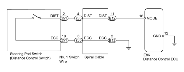
INSPECTION PROCEDURE
CAUTION:
The vehicle is equipped with an SRS (Supplemental Restraint System) which includes components such as airbags. Before servicing (including removal or installation of parts), be sure to read the Precaution for the SRS
 .
.
NOTICE:
When the distance control ECU is replaced with a new one, initialization must be performed
.
PROCEDURE
|
1. |
READ VALUE USING TECHSTREAM (VEHICLE DISTANCE) |
(a) Using the Techstream, read the Data List.
Radar Cruise
|
Tester Display |
Measurement Item/Range |
Normal Condition |
Diagnostic Note |
|---|---|---|---|
|
Car Dist Time Setting |
Vehicle distance time setting condition / SHORT, LONG, MID or NO |
Vehicle distance selected by steering pad switch (distance control switch) |
- |
OK:
Normal conditions listed above are displayed.
|

|
2. |
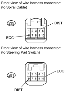
CHECK NO. 1 SWITCH WIRE |
|
(a) Disconnect the z35 and z51 No. 1 switch wire connectors. |
(b) Measure the resistance according to the value(s) in the table below.
Standard Resistance:
|
Tester Connection |
Condition |
Specified Condition |
|---|---|---|
|
z35-4 (DIST) - z51-2 (DIST) |
Always |
Below 1 Ω |
|
z35-6 (ECC) - z51-10 (ECC) |
Always |
Below 1 Ω |
|
|
3. |
INSPECT STEERING PAD SWITCH |
(a) Disconnect the z35 steering pad switch connector from the spiral cable.
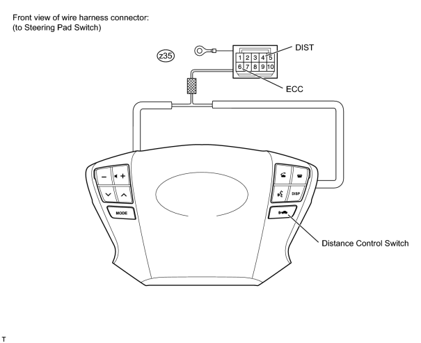
(b) Measure the resistance according to the value(s) in the table below.
Standard Resistance:
|
Tester Connection |
Switch Condition |
Specified Condition |
|---|---|---|
|
z35-4 (DIST) - z35-6 (ECC) |
Distance control switch on (pushed) |
Below 1 Ω |
|
Distance control switch off (pushed again) |
1 MΩ or higher |
|
|
4. |
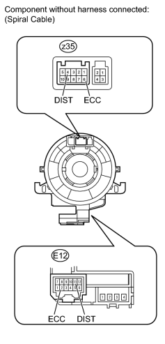
INSPECT SPIRAL CABLE |
|
(a) Check the spiral cable and connector for scratches, cracks, dents and chips. If any defects are found, replace the spiral cable with a new one. |
(b) Check the spiral cable.
(1) Set the spiral cable to the center position
.
(2) After setting the spiral cable to the center position, rotate the spiral cable 2.5 times clockwise, and measure the resistance according to the value(s) in the table below. Then rotate the spiral cable 5 times counterclockwise, and measure the resistance according to the value(s) in the table below.
Standard Resistance:
|
Tester Connection |
Condition |
Specified Condition |
|---|---|---|
|
z35-4 (DIST) - E12-11 (DIST) |
Always |
Below 1 Ω |
|
z35-6 (ECC) - E12-2 (ECC) |
(3) After setting the spiral cable to the center position, rotate the spiral cable 2.5 times clockwise. Then while rotating the spiral cable 5 times counterclockwise, measure the resistance according to the value(s) in the table below.
NOTICE:
As the spiral cable may break, do not rotate the spiral cable more than the specified amount.
Standard Resistance:
|
Tester Connection |
Condition |
Specified Condition |
|---|---|---|
|
z35-4 (DIST) - E12-11 (DIST) |
Always |
Below 1 Ω |
|
z35-6 (ECC) - E12-2 (ECC) |
|
|
5. |
CHECK HARNESS AND CONNECTOR (SPIRAL CABLE - DISTANCE CONTROL ECU AND BODY GROUND) |

|
(a) Disconnect the E86 distance control ECU connector. |
(b) Disconnect the E12 spiral cable connector.
(c) Measure the resistance according to the value(s) in the table below.
Standard Resistance:
|
Tester Connection |
Condition |
Specified Condition |
|---|---|---|
|
E12-2 (ECC) - Body ground |
Always |
Below 1 Ω |
|
E12-11 (DIST) - E86-16 (MODE) |
Always |
Below 1 Ω |
|
E12-11 (DIST) - Body ground |
Always |
10 kΩ or higher |
|

|

|