| Last Modified: 11-27-2007 | 1.6 A | |
| Service Category: Steering | Section: Steering Column | |
| Model Year: 2008 | Model: LX570 | Doc ID: RM0000039SI005X |
| Title: STEERING COLUMN: STEERING COLUMN ASSEMBLY: REMOVAL (2008 LX570) | ||
REMOVAL
CAUTION:
Some of these service operations affect the SRS airbag system. Read the precautionary notices concerning the SRS airbag system before servicing the steering column
 .
.
1. FRONT WHEELS FACING STRAIGHT AHEAD
2. DISCONNECT CABLE FROM NEGATIVE BATTERY TERMINAL
(a) Disable the Autoaway/Return function by changing the customize parameter
.
NOTICE:
Record the current customize parameter setting (whether the AUTO TILT AWAY function is enabled or disabled) in order to restore the current setting after finishing the operation.
HINT:
Performing the above operation causes the AUTO TILT AWAY function to be disabled when the engine switch is turned off.
(b) Turn the engine switch on (IG). Operate the tilt and telescopic switch to fully extend and lower the steering column assembly.
(c) Turn the engine switch off and disconnect the cable from the negative (-) battery terminal.
CAUTION:
Wait at least 90 seconds after disconnecting the cable from the negative (-) battery terminal to disable the SRS system.
w/ Navigation system:
NOTICE:
After the engine switch is turned off, the HDD navigation system requires approximately 6 minutes to record various types of memory and settings. As a result, after turning the engine switch off, wait 6 minutes or more before disconnecting the cable from the negative (-) battery terminal.
3. REMOVE LOWER NO. 3 STEERING WHEEL COVER
4. REMOVE LOWER NO. 2 STEERING WHEEL COVER
5. REMOVE STEERING PAD
6. REMOVE STEERING WHEEL ASSEMBLY
7. REMOVE LOWER STEERING COLUMN COVER
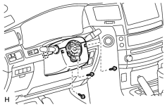
(a) Remove the 3 screws.
(b) Detach the 2 claws to remove the lower steering column cover.
NOTICE:
Do not damage the tilt and telescopic switch.
8. REMOVE UPPER STEERING COLUMN COVER
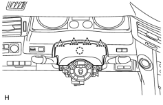
(a) Detach the 4 clips.
(b) Detach the claw to remove the upper steering column cover.
9. REMOVE TILT AND TELESCOPIC MANUAL SWITCH
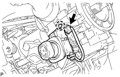
(a) Disconnect the switch connector.
(b) Using a screwdriver, detach the claw and pull out the switch.
HINT:
Tape the screwdriver tip before use.
NOTICE:
Pushing on the claw too hard will break the claw.
10. REMOVE COMBINATION SWITCH ASSEMBLY WITH SPIRAL CABLE SUB-ASSEMBLY
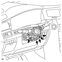
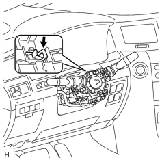
(a) Disconnect the 5 connectors from the turn signal switch with spiral cable.
|
(b) Using pliers, grip the claws of the clamp and remove the turn signal switch with spiral cable from the steering column. |
11. REMOVE LOWER INSTRUMENT PANEL PAD SUB-ASSEMBLY LH
12. REMOVE INNER NO. 1 INSTRUMENT PANEL BRACKET COVER LH
13. REMOVE INSTRUMENT SIDE PANEL LH
14. REMOVE NO. 1 INSTRUMENT PANEL REGISTER ASSEMBLY
15. REMOVE NO. 3 INSTRUMENT PANEL REGISTER ASSEMBLY
16. REMOVE NO. 1 SWITCH HOLE BASE
17. REMOVE INSTRUMENT CLUSTER FINISH PANEL SUB-ASSEMBLY
18. REMOVE FRONT DOOR SCUFF PLATE LH
19. REMOVE NO. 1 INSTRUMENT PANEL UNDER COVER SUB-ASSEMBLY
20. REMOVE COWL SIDE TRIM BOARD LH
21. REMOVE LOWER NO. 1 INSTRUMENT PANEL FINISH PANEL
22. REMOVE INSTRUMENT PANEL BOX ASSEMBLY
23. REMOVE DRIVER SIDE KNEE AIRBAG ASSEMBLY
24. DISCONNECT WIRE HARNESS PROTECTOR AND WIRE HARNESS
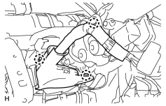
(a) Detach the 3 claws to disconnect the wire harness protector and wire harness.
25. REMOVE NO. 3 AIR DUCT SUB-ASSEMBLY
26. REMOVE STEERING COLUMN ASSEMBLY
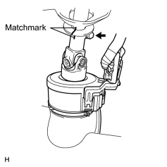
(a) Put matchmarks on the steering actuator and steering column.
(b) Remove the bolt.
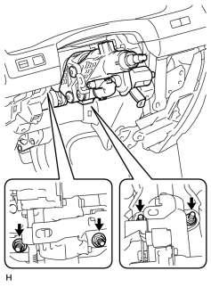
|
(c) Remove the 4 nuts and steering column. |
27. DISCONNECT STEERING ACTUATOR ASSEMBLY
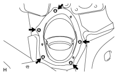
28. REMOVE STEERING COLUMN HOLE COVER SUB-ASSEMBLY
|
(a) Remove the 4 bolts, nut and steering column hole cover. |
29. DISCONNECT NO. 2 STEERING INTERMEDIATE SHAFT
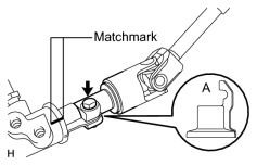
(a) Loosen the bolt and remove the No. 2 intermediate shaft.
HINT:
If the dust cover is removed/installed or replaced, place matchmarks on the dust cover and steering link.
NOTICE:
It is possible to install the intermediate shaft to the same position it was removed from without placing matchmarks due to the dust cover part labeled A. Therefore, do not remove the dust cover from the steering link.

|

|