- Fuse (STOP, IGN, ECU-IG No. 2)
- Stop light switch
- Brake light relay
- Stop light control relay
- Master cylinder solenoid (skid control ECU)
- Harness or connector
- ECM
| Last Modified: 11-27-2007 | 1.6 C | |
| Service Category: Engine/Hybrid System | Section: Cruise Control | |
| Model Year: 2008 | Model: LX570 | Doc ID: RM000003FEH000X |
| Title: CRUISE CONTROL: DYNAMIC RADAR CRUISE CONTROL SYSTEM: DESCRIPTION (2008 LX570) | ||
|
DTC |
P0571 |
Stop Light Switch Circuit Malfunction |
DESCRIPTION
The ECM receives the brake demand signal from the stop light switch and transmits it to the master cylinder solenoid (skid control ECU). The master cylinder solenoid (skid control ECU) receives the signal from the ECM and operates the brake actuator.
|
DTC Code |
DTC Detection Condition |
Trouble Area |
|---|---|---|
|
P0571 |
This trouble code is output when the ECM detects the brake light relay error signal from the master cylinder solenoid (skid control ECU) for 0.2 sec. or more while the dynamic radar cruise control is in operation. |
|
WIRING DIAGRAM
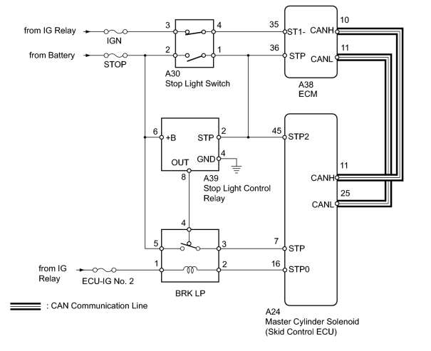
INSPECTION PROCEDURE
PROCEDURE
|
1. |
INSPECT FUSE (STOP, IGN, ECU-IG No. 2) |
(a) Remove the STOP and IGN fuses from the engine room relay block.
(b) Remove the ECU-IG No. 2 fuse from the cowl side junction block LH.
(c) Measure the resistance according to the value(s) in the table below.
Standard Resistance:
|
Tester Connection |
Condition |
Specified Condition |
|---|---|---|
|
STOP fuse |
Always |
Below 1 Ω |
|
IGN fuse |
||
|
ECU-IG No. 2 fuse |
|

|
2. |
READ VALUE USING TECHSTREAM (STOP LIGHT SWITCH) |
(a) Using the Techstream, read the Data List.
Radar Cruise
|
Tester Display |
Measurement Item/Range |
Normal Condition |
Diagnostic Note |
|---|---|---|---|
|
Stop Light SW M-CPU |
Stop light switch signal (Main CPU) / ON or OFF |
ON: Brake pedal depressed OFF: Brake pedal released |
- |
|
Stop Light SW-1 S-CPU |
Stop light switch signal (Sub CPU) / ON or OFF |
ON: Brake pedal depressed OFF: Brake pedal released |
- |
|
Stp Light SW S2-CPU |
Stop light switch signal (Sub CPU) / ON or OFF |
ON: Brake pedal depressed OFF: Brake pedal released |
- |
OK:
Normal conditions listed above are displayed.
|
|
3. |
INSPECT BRAKE LIGHT RELAY (BRK LP) |
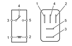
|
(a) Remove the brake light relay from the engine room relay block. |
(b) Measure the resistance according to the value(s) in the table below.
Standard Resistance:
|
Tester Connection |
Condition |
Specified Condition |
|---|---|---|
|
3 - 4 |
Battery voltage is applied to terminals 1 and 2 |
10 kΩ higher |
|
Battery voltage is not applied to terminals 1 and 2 |
Below 1 Ω |
|
|
3 - 5 |
Battery voltage is not applied to terminals 1 and 2 |
10 kΩ higher |
|
Battery voltage is applied to terminals 1 and 2 |
Below 1 Ω |
|
|
4. |
CHECK HARNESS AND CONNECTOR (STOP LIGHT CONTROL RELAY - BATTERY AND BODY GROUND) |
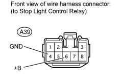
|
(a) Disconnect the A39 stop light control relay connector. |
(b) Measure the voltage according to the value(s) in the table below.
Standard Voltage:
|
Tester Connection |
Condition |
Specified Condition |
|---|---|---|
|
A39-6 (+B) - Body ground |
Always |
11 to 14 V |
(c) Measure the resistance according to the value(s) in the table below.
Standard Resistance:
|
Tester Connection |
Condition |
Specified Condition |
|---|---|---|
|
A39-4 (GND) - Body ground |
Always |
Below 1 Ω |
|
|
5. |
CHECK HARNESS AND CONNECTOR (STOP LIGHT CONTROL RELAY - STOP LIGHT SWITCH) |
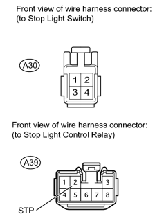
|
(a) Disconnect the A39 stop light control relay connector. |
(b) Disconnect the A30 stop light switch connector.
(c) Measure the resistance according to the value(s) in the table below.
Standard Resistance:
|
Tester Connection |
Condition |
Specified Condition |
|---|---|---|
|
A30-1 - A39-2 (STP) |
Always |
Below 1 Ω |
|
A30-1 - Body ground |
Always |
10 kΩ higher |
|
|
6. |
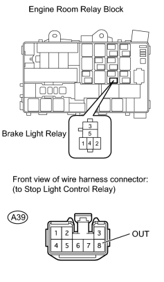
CHECK HARNESS AND CONNECTOR (STOP LIGHT CONTROL RELAY - BRAKE LIGHT RELAY) |
|
(a) Disconnect the A39 stop light control relay connector. |
(b) Remove the brake light relay from the engine room relay block.
(c) Measure the resistance according to the value(s) in the table below.
Standard Resistance:
|
Tester Connection |
Condition |
Specified Condition |
|---|---|---|
|
A39-8 (OUT) - Brake light relay terminal 4 |
Always |
Below 1 Ω |
|
A39-8 (OUT) - Body ground |
Always |
10 kΩ higher |
|
|
7. |
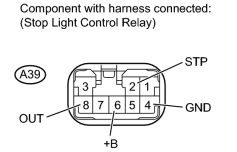
CHECK STOP LIGHT CONTROL RELAY |
|
(a) Remove the stop light control relay with its connector still connected
|

(b) Measure the voltage according to the value(s) in the table below.
Standard Voltage:
|
Tester Connection |
Switch Condition |
Specified Condition |
|---|---|---|
|
A39-6 (+B) - A39-4 (GND) |
Always |
11 to 14 V |
|
A39-2 (STP) - Body ground |
Stop light switch on (Brake pedal depressed) |
11 to 14 V |
|
Stop light switch off (Brake pedal released) |
Below 1 V |
|
|
A39-8 (OUT) - Body ground |
Stop light switch on (Brake pedal depressed) |
11 to 14 V |
|
Stop light switch off (Brake pedal released) |
Below 1 V |
|
|
8. |
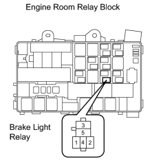
CHECK HARNESS AND CONNECTOR (BRAKE LIGHT RELAY - BATTERY) |
|
(a) Remove the brake light relay from the engine room relay block. |
(b) Measure the voltage according to the value(s) in the table below.
Standard Voltage:
|
Tester Connection |
Switch Condition |
Specified Condition |
|---|---|---|
|
Brake light relay terminal 1 - Body ground |
Engine switch on (IG) |
11 to 14 V |
|
Brake light relay terminal 5 - Body ground |
|
|
9. |
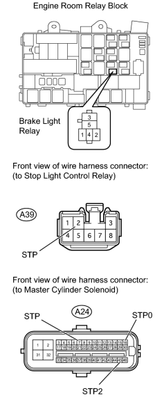
CHECK HARNESS AND CONNECTOR (BRK LP, STOP LIGHT CONTROL RELAY - MASTER CYLINDER SOLENOID) |
|
(a) Disconnect the A24 master cylinder solenoid (skid control ECU) connector. |
(b) Remove the brake light relay from the engine room relay block.
(c) Disconnect the A39 stop light control relay connector.
(d) Measure the resistance according to the value(s) in the table below.
Standard Resistance:
|
Tester Connection |
Condition |
Specified Condition |
|---|---|---|
|
Brake light relay terminal 2 - A24-16 (STP0) |
Always |
Below 1 Ω |
|
A39-2 (STP) - A24-45 (STP2) |
||
|
Brake light relay terminal 3 - A24-7 (STP) |
||
|
Brake light relay terminal 2 - Body ground |
Always |
10 kΩ higher |
|
A39-2 (STP) - Body ground |
||
|
Brake light relay terminal 3 - Body ground |
|
|
10. |
INSPECT STOP LIGHT SWITCH |
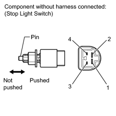
|
(a) Disconnect the A30 stop light switch connector. |
(b) Measure the resistance according to the value(s) in the table below.
Standard Resistance:
|
Tester Connection |
Switch Condition |
Specified Condition |
|---|---|---|
|
1 - 2 |
Pin not pushed |
Below 1 Ω |
|
Pin pushed |
10 kΩ higher |
|
|
3 - 4 |
Pin not pushed |
10 kΩ higher |
|
Pin pushed |
Below 1 Ω |
|
|
11. |
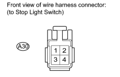
CHECK HARNESS AND CONNECTOR (STOP LIGHT SWITCH - BATTERY) |
|
(a) Disconnect the A30 stop light switch connector. |
(b) Measure the voltage according to the value(s) in the table below.
Standard Voltage:
|
Tester Connection |
Switch Condition |
Specified Condition |
|---|---|---|
|
A30-2 - Body ground |
Engine switch on (IG) |
11 to 14 V |
|
A30-3 - Body ground |
|
|
12. |
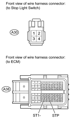
CHECK HARNESS AND CONNECTOR (STOP LIGHT SWITCH - ECM) |
|
(a) Disconnect the A38 ECM connector. |
(b) Disconnect the A30 stop light switch connector.
(c) Measure the resistance according to the value(s) in the table below.
Standard Resistance:
|
Tester Connection |
Condition |
Specified Condition |
|---|---|---|
|
A30-4 - A38-35 (ST1-) |
Always |
Below 1 Ω |
|
A30-1 - A38-36 (STP) |
||
|
A30-1 - Body ground |
Always |
10 kΩ higher |
|
A30-4 - Body ground |
|

|

|