| Last Modified: 11-27-2007 | 1.6 G | |
| Service Category: Vehicle Exterior | Section: Lighting (ext) | |
| Model Year: 2008 | Model: LX570 | Doc ID: RM0000038XQ002X |
| Title: LIGHTING (EXT): RELAY: ON-VEHICLE INSPECTION (2008 LX570) | ||
ON-VEHICLE INSPECTION
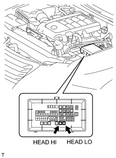
1. INSPECT HEADLIGHT RELAY (HEAD HI, HEAD LO)
(a) Remove the engine room side cover LH
 .
.
|
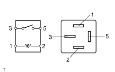
(b) Remove the headlight relay from the engine room relay box. |
|
(c) Measure the resistance according to the value(s) in the table below. Standard Resistance:
If the result is not as specified, replace the relay. |
(d) Install the headlight relay to the engine room relay box.
(e) Install the engine room side cover LH
.
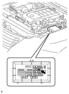
2. INSPECT FOG LIGHT RELAY (FR FOG)
(a) Remove the engine room side cover LH
.
|
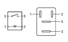
(b) Remove the fog light relay from the engine room relay box. |
|
(c) Measure the resistance according to the value(s) in the table below. Standard Resistance:
If the result is not as specified, replace the relay. |
(d) Install the fog light relay to the engine room relay box.
(e) Install the engine room side cover LH
.
3. INSPECT STOP LIGHT CONTROL RELAY ASSEMBLY
(a) Remove the No. 1 under cover
.
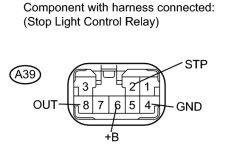
|
(b) Measure the voltage according to the value(s) in the table below. Standard Voltage:
If *1 and *2 are normal and *3 is not as specified, replace the stop light control relay assembly. |
(c) Install the No. 1 under cover
.

|

|