| Last Modified: 11-27-2007 | 1.6 J | |
| Service Category: Vehicle Exterior | Section: Door/Hatch | |
| Model Year: 2008 | Model: LX570 | Doc ID: RM000003FSO000X |
| Title: DOOR / HATCH: TAIL GATE CLOSER SYSTEM: WIRING DIAGRAM (2008 LX570) | ||
|
Tail Gate does not Open with Back Door Remote Control |
WIRING DIAGRAM
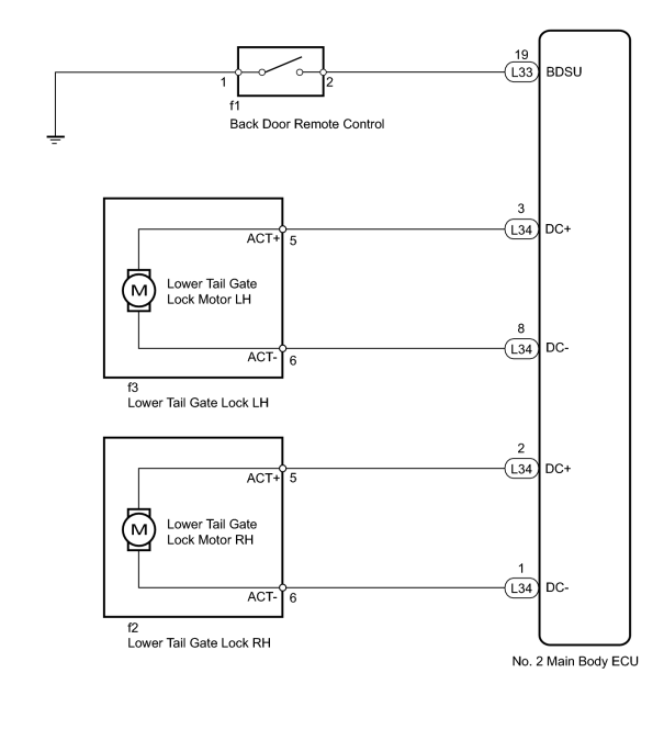
INSPECTION PROCEDURE
PROCEDURE
|
1. |
PERFORM ACTIVE TEST USING TECHSTREAM (LOWER TAIL GATE LOCK) |
(a) Select the Active Test, use the Techstream to generate a control command, and check that the lower tail gate lock operates.
Body No. 4
|
Tester Display |
Test Part |
Control Range |
Diagnostic Note |
|---|---|---|---|
|
Tail Gate Panel Open |
Lower tail gate lock |
ON or OFF |
The back door must be open. |
OK:
Lower tail gate lock operates normally.
|

|
2. |
READ VALUE USING TECHSTREAM (BACK DOOR REMOTE CONTROL) |
(a) Check the Data List for proper functioning of the back door remote control.
Body No. 4
|
Tester Display |
Measurement Item/Range |
Normal Condition |
Diagnostic Note |
|---|---|---|---|
|
Handle Switch of tail gate panel |
Back door remote control signal/ON or OFF |
ON: Back door remote control pulled OFF: Back door remote control free |
- |
OK:
The display is as specified in the normal condition.
|
|
3. |
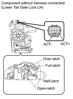
INSPECT LOWER TAIL GATE LOCK ASSEMBLY |
|
(a) for LH: (1) Remove the lower tail gate lock LH
(2) Set the lower tail gate lock LH to the full-latch position. (3) Apply battery voltage and check the operation of the lower tail gate lock motor LH. OK:
|
|
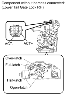
(b) for RH: (1) Remove the lower tail gate lock RH
(2) Set the lower tail gate lock RH to the full-latch position. (3) Apply battery voltage and check the operation of the lower tail gate lock motor RH. OK:
|
|
|
4. |
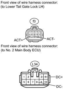
CHECK HARNESS AND CONNECTOR (LOCK - ECU) |
|
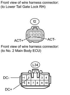
(a) for LH: (1) Disconnect the f3 lock connector. (2) Disconnect the L34 ECU connector. (3) Measure the resistance according to the value(s) in the table below. Standard Resistance:
|
|
(b) for RH: (1) Disconnect the f2 lock connector. (2) Disconnect the L34 ECU connector. (3) Measure the resistance according to the value(s) in the table below. Standard Resistance:
|
|
|
5. |
INSPECT BACK DOOR REMOTE CONTROL |
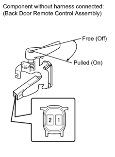
(a) Remove the back door remote control
 .
.
(b) Measure the resistance according to the value(s) in the table below.
Standard Resistance:
|
Tester Connection |
Switch Condition |
Specified Condition |
|---|---|---|
|
1 - 2 |
Back door remote control is pulled (on) |
Below 1 Ω |
|
1 - 2 |
Back door remote control is free (off) |
10 kΩ or higher |
|
|
6. |
CHECK HARNESS AND CONNECTOR (CONTROL - ECU AND BODY GROUND) |
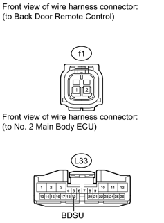
(a) Disconnect the f1 control connector.
(b) Disconnect the L33 ECU connector.
(c) Measure the resistance according to the value(s) in the table below.
Standard Resistance:
|
Tester Connection |
Condition |
Specified Condition |
|---|---|---|
|
f1-2 - L33-19 (BDSU) |
Always |
Below 1 Ω |
|
f1-1 - Body ground |
Always |
Below 1 Ω |
|
f1-2 - Body ground |
Always |
10 kΩ or higher |
|

|

|