INSTALLATION
Removal / installation
| 1. INSTALL PARK/NEUTRAL POSITION SWITCH |

Install the park/neutral position switch to the manual valve shaft.
Temporarily install the 2 bolts.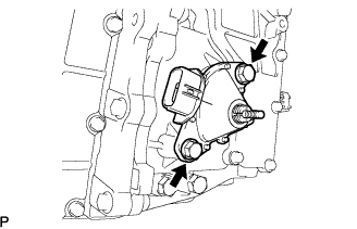

Place new lock plate and tighten the nut.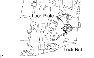
- Torque:
- 6.9 N*m{ 70 kgf*cm , 61 in.*lbf }
Temporarily install the control shaft lever.
Turn the lever counterclockwise until it stops, then turn it clockwise 2 notches.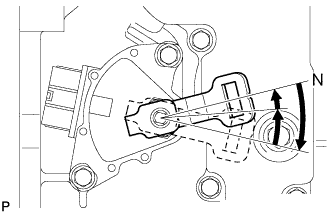
Remove the control shaft lever.
Align the protruding part with the neutral basic line.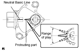
- NOTICE:
- There is play on the nut stopper side (protruding part). Align the center point of the range of the play with the neutral basic line.
Tighten the 2 bolts in the order shown in the illustration.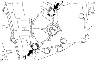
- Torque:
- 13 N*m{ 133 kgf*cm , 10 ft.*lbf }
Using a screwdriver, stake the nut with the lock plate.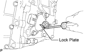
Install the control shaft lever, washer and nut.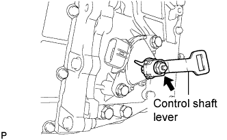
- Torque:
- 6.9 N*m{ 70 kgf*cm , 61 in.*lbf }
| 2. CONNECT TRANSMISSION CONTROL CABLE ASSEMBLY |
Move the shift lever to the N position.
Install a new clip to the control bracket.
Install the control cable to the control bracket.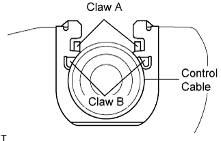
- NOTICE:
- Make sure that the A claws on the clip are securely fit into the bracket holes.
- Make sure that the cable is securely installed inside of the B claws of the clip.
- Make sure that the A claws on the clip are securely fit into the bracket holes.
Connect the park/neutral position switch connector.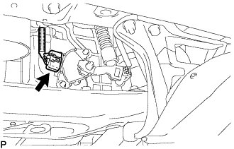
Move the control shaft lever to the N position.
Temporarily install the control cable to the control shaft lever with the nut.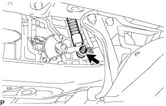
Lightly push up the control cable end.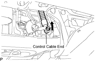
- NOTICE:
- Do not push the control cable end excessively.
Release your hand from the control cable end and then fully tighten the nut.
- Torque:
- 15 N*m{ 150 kgf*cm , 11 ft.*lbf }
| 3. INSTALL OIL COOLER TUBE SUB-ASSEMBLY |
Using SST and a wrench, tighten the 2 new oil cooler tubes.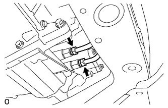
- SST
- 09023-12701
- Torque:
- 34 N*m{ 350 kgf*cm , 25 ft.*lbf }
Install the tube support bracket to the control cable bracket with the bolt.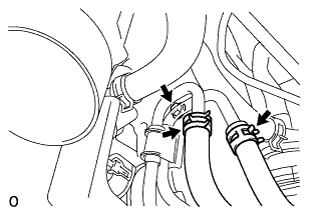
- Torque:
- 8.2 N*m{ 84 kgf*cm , 73 in.*lbf }
Install the clamp to the tube support bracket with the bolt.
- Torque:
- 7.0 N*m{ 71 kgf*cm , 62 in.*lbf }
Install the oil cooler hoses to the oil cooler tubes.
| 4. ADD AND INSPECT HYBRID TRANSAXLE FLUID |
Fill oil.
- Transaxle fluid quantity:
- 4.2 L (4.4 US qts, 3.7 Imp. qts.)
Check that the oil surface is within 5 mm (0.20 in.) from the lowest position of the inner surface of the differential filler plug opening.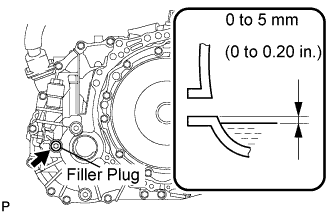
- NOTICE:
- Keep the oil temperature at 5°C (41°F) or higher.
- Stop the vehicle on a flat road.
- Recheck the transaxle oil level after driving when exchanging oil.
- Insufficient or excessive amounts of transaxle oil may be the cause of some trouble.
- Keep the oil temperature at 5°C (41°F) or higher.
Using a socket hexagon wrench 10 mm, temporarily tighten the filler plug and gasket.
Connect the intelligent tester to the DLC3.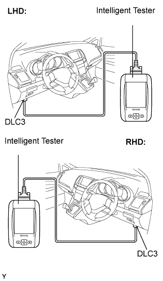
Turn the ignition switch to the ON position.
Select the inspection mode. (Click here)
On the tester, enter the following menus: Powertrain / Hybrid Control / Active test / Inspection Mod 1.
Turn the ignition switch to the ON position and turn the tester on.
- HINT:
- Operate the oil pump for 1 minute.
Using a socket hexagon wrench 10 mm, remove the filler plug and gasket.
Fill oil.
Check that the oil surface is within 5 mm (0.20 in.) from the lowest position of the inner surface of the differential filler plug opening.
- NOTICE:
- Keep the oil temperature at 5°C (41°F) or higher.
- Stop the vehicle on a flat road.
- Recheck the transaxle oil level after driving when exchanging oil.
- Insufficient or excessive amounts of transaxle oil may be the cause of some trouble.
- Keep the oil temperature at 5°C (41°F) or higher.
Check for leaks if the quantity of oil is low.
Using a socket hexagon wrench 10 mm, install the filler plug, and a new gasket.
- Torque:
- 39 N*m{ 398 kgf*cm , 29 ft.*lbf }
| 5. INSPECT SHIFT LEVER POSITION |
Apply the parking brake.
Lock the wheels with chocks to secure the vehicle.
Put the vehicle into the READY-on state.
Move the shift lever to the D position and release the brake pedal.
- NOTICE:
- Be sure to apply the parking brake and lock the wheels with chocks to secure the vehicle.
Slowly move the shift lever to the N position and measure moving distance (A) of the shift lever from the original point to the gear activation point.
- NOTICE:
- Be sure to move the shift lever slowly.
Move the shift lever to the R position and release the brake pedal.
- NOTICE:
- Be sure to apply the parking brake and lock the wheels with chocks to secure the vehicle.
Slowly move the shift lever to the N position and measure moving distance (B) of the shift lever from the original point to the vehicle activation point.
- NOTICE:
- Be sure to move the shift lever slowly.
Check that moving distances (A) and (B) shown in the illustration are almost the same.
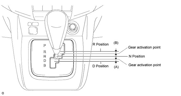
- HINT:
- If moving distances (A) and (B) are almost the same, adjustment of the shift lever position is not necessary.
- If moving distance (A) is shorter than (B), perform adjustment of the shift lever position [*1].
- If moving distance (B) is shorter than (A), perform adjustment of the shift lever position [*2].
- If moving distances (A) and (B) are almost the same, adjustment of the shift lever position is not necessary.
| 6. ADJUST SHIFT LEVER POSITION |
If moving distance (A) is shorter than (B) [*1]:
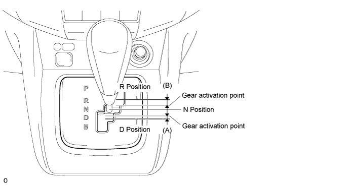
- HINT:
- If the shift lever is moved from the R to N position, the moving distance of the shift lever from the original point to the gear activation point becomes longer.
Move the shift lever to the N position.
Loosen the 2 bolts.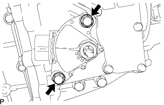
Slightly turn the park/neutral position switch counterclockwise.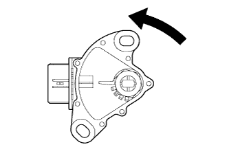
Tighten the 2 bolts in the order shown in the illustration.
- Torque:
- 13 N*m{ 133 kgf*cm , 10 ft.*lbf }
Recheck the shift lever position.
If moving distance (B) is shorter than (A) [*2]:
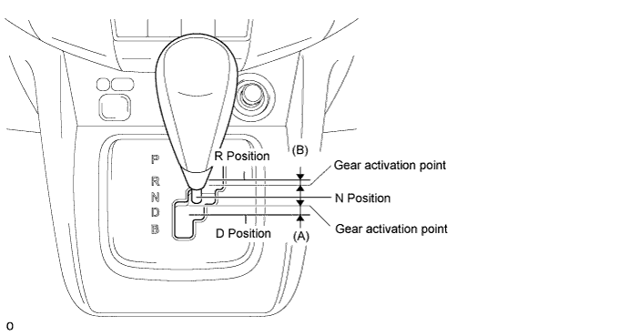
- HINT:
- If the shift lever is moved from the D to N position, the moving distance of the shift lever from the original point to the gear activation point becomes longer.
Move the shift lever to the N position.
Loosen the 2 bolts.
Slightly turn the park/neutral position switch clockwise.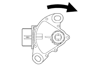
Tighten the 2 bolts in the order shown in the illustration.
- Torque:
- 13 N*m{ 133 kgf*cm , 10 ft.*lbf }
Recheck the shift lever position.
| 7. INSPECT SHIFT LEVER OPERATION |
While moving the shift lever from the N position to each position, check that the lever moves smoothly and that the shift position indicator comes on properly according to the shift lever position.
Put the vehicle into the READY-on state and check the following:
When the shift lever is moved to the D position, the vehicle moves forward.
When the shift lever is moved to the R position, the buzzer sounds and the vehicle moves in reverse.
- NOTICE:
- The vehicle should not move when the shift position indicator is off.
| 8. INSTALL ENGINE UNDER COVER NO.1 |
Install the 6 bolts, 2 screws, 2 clips and engine under cover.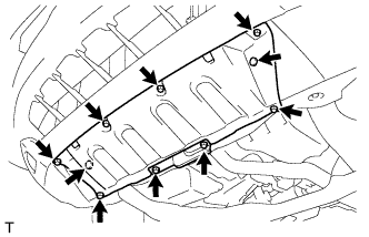
| 9. CONNECT CABLE TO NEGATIVE BATTERY TERMINAL |
| 10. PERFORM INITIALIZATION |