INSTALLATION
Removal / installation
| 1. INSTALL SHIFT LEVER |

Install the floor shift assembly with the 4 nuts.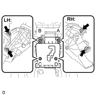

- Torque:
- 12 N*m{ 122 kgf*cm , 9 ft.*lbf }
- NOTICE:
- Tighten them in the order, A, B, C and D.
Install the pattern select switch connector, the shift lock control computer connector and the indicator light wire connector.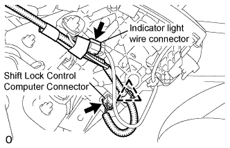
| 2. CONNECT TRANSMISSION CONTROL CABLE ASSEMBLY |
Connect the socket of the transmission control cable assembly to the shift lever assembly.
Turn the socket of the transmission control cable assembly clockwise and install the stopper cap.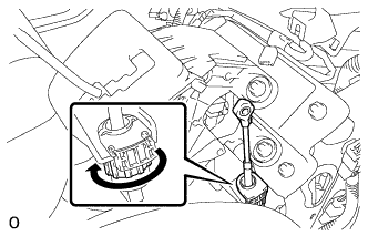
- NOTICE:
- Make sure that the transmission control cable assembly (socket) is firmly secured to the shift lever assembly.
Push the stopper cap to the socket as shown in the illustration.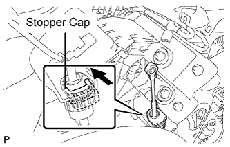
Connect the control cable end to the shift lever assembly.
- NOTICE:
- Install the transmission control cable assembly with the graduated cuts to face upward to prevent torsion of the inner cable.
- Push the cable end to the bottom of the pin.
- Confirm that the connection between the socket and the shift lock control unit is fixed.
- Install the transmission control cable assembly with the graduated cuts to face upward to prevent torsion of the inner cable.
| 3. INSTALL FLOOR CARPET COVER CENTER LH |
Slide the floor carpet cover center LH to the rear of the vehicle, and engage the 2 claws to the instrument panel finish panel lower center at the floor carpet cover center LH.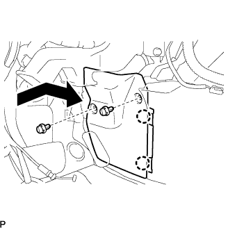
Install the 2 clips and the floor carpet cover center LH.
| 4. INSTALL FLOOR CARPET COVER CENTER RH |
- HINT:
- Use the same procedures for the RH side and the LH side.
| 5. INSTALL GLOVE COMPARTMENT DOOR ASSEMBLY |
Connect the connectors.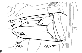
Install the 2 bolts <A>, the 2 screws <C>, and the glove compartment door assembly.
| 6. INSTALL INSTRUMENT PANEL UNDER COVER SUB-ASSEMBLY NO.2 |
Connect the connectors.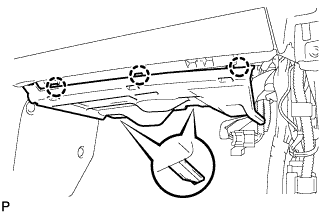
Engage the 3 claws and install the instrument panel No.2 under cover sub-assembly.
| 7. INSTALL INSTRUMENT PANEL FINISH PANEL SUB-ASSEMBLY LOWER |
Connect the connectors.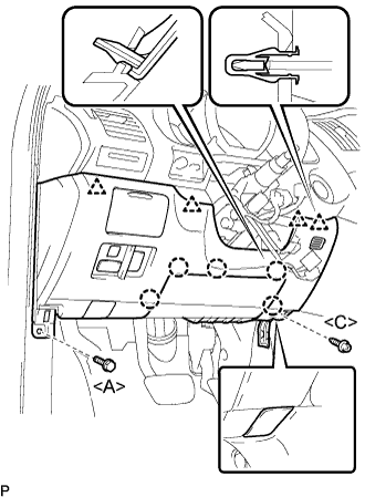
Engage the 5 claws and the 4 clips.
Connect the hood lock control cable assembly.
Install the bolt <A>, the screw <C>, and the instrument panel finish panel sub-assembly lower.
| 8. INSTALL COWL SIDE TRIM SUB-ASSEMBLY LH |
Install the 2 clips and the cowl side trim sub-assembly LH.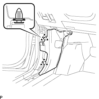
| 9. INSTALL COWL SIDE TRIM SUB-ASSEMBLY RH |
- HINT:
- Use the same procedures for the RH side and the LH side.
| 10. INSTALL FRONT DOOR SCUFF PLATE RH |
- HINT:
- Use the same procedures for the RH side and the LH side.
| 11. INSTALL FRONT DOOR SCUFF PLATE LH |
Connect the connector. (w/ illumination scuff plate)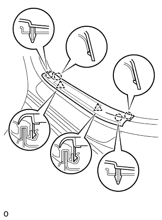
Engage the 4 claws and 2 clips, and install the rear door scuff plate.
| 12. INSTALL INSTRUMENT PANEL FINISH PANEL LOWER |
Connect the connectors.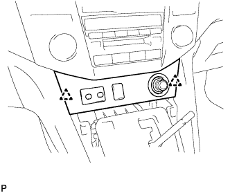
Engage the 2 clips and install the instrument panel finish panel lower.
| 13. INSTALL CONSOLE PANEL UPPER FRONT |
Engage the 4 clips and install the console panel upper front.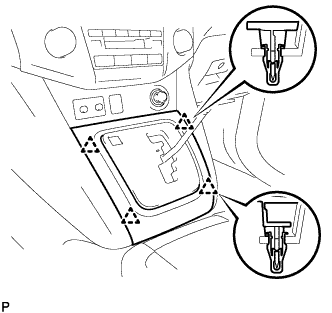
| 14. INSTALL SHIFT LEVER KNOB |
Install the shift lever knob.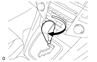
| 15. INSTALL BATTERY NEGATIVE TERMINAL |
| 16. INSPECT SHIFT LEVER POSITION |
Apply the parking brake.
Lock the wheels with chocks to secure the vehicle.
Put the vehicle into the READY-on state.
Move the shift lever to the D position and release the brake pedal.
- NOTICE:
- Be sure to apply the parking brake and lock the wheels with chocks to secure the vehicle.
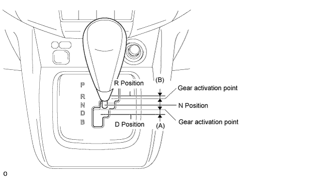
Slowly move the shift lever to the N position and measure moving distance (A) of the shift lever from the original point to the gear activation point.
- NOTICE:
- Be sure to move the shift lever slowly.
Move the shift lever to the R position and release the brake pedal.
- NOTICE:
- Be sure to apply the parking brake and lock the wheels with chocks to secure the vehicle.
Slowly move the shift lever to the N position and measure moving distance (B) of the shift lever from the original point to the vehicle activation point.
- NOTICE:
- Be sure to move the shift lever slowly.
Check that moving distances (A) and (B) shown in the illustration are almost the same.
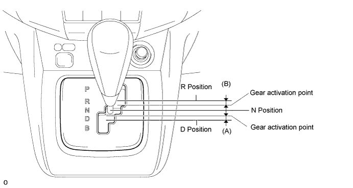
- HINT:
- If moving distances (A) and (B) are almost the same, adjustment of the shift lever position is not necessary.
- If moving distance (A) is shorter than (B), perform adjustment of the shift lever position [*1].
- If moving distance (B) is shorter than (A), perform adjustment of the shift lever position [*2].
- If moving distances (A) and (B) are almost the same, adjustment of the shift lever position is not necessary.
| 17. ADJUST SHIFT LEVER POSITION |
If moving distance (A) is shorter than (B) [*1]:
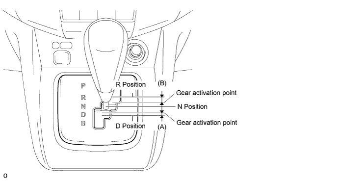
- HINT:
- If the shift lever is moved from the R to N position, the moving distance of the shift lever from the original point to the gear activation point becomes longer.
Move the shift lever to the N position.
Loosen the 2 bolts.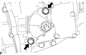
Slightly turn the park/neutral position switch counterclockwise.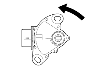
Tighten the 2 bolts in the order shown in the illustration.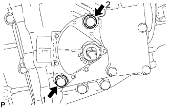
- Torque:
- 13 N*m{ 133 kgf*cm , 10 ft.*lbf }
Recheck the shift lever position.
If moving distance (B) is shorter than (A) [*2]:
- HINT:
- If the shift lever is moved from the D to N position, the moving distance of the shift lever from the original point to the gear activation point becomes longer.
Move the shift lever to the N position.
Loosen the 2 bolts.
Slightly turn the park/neutral position switch clockwise.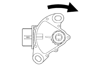
Tighten the 2 bolts in the order shown in the illustration.
- Torque:
- 13 N*m{ 133 kgf*cm , 10 ft.*lbf }
Recheck the shift lever position.
| 18. INSPECT SHIFT LEVER OPERATION |
While moving the shift lever from the N position to each position, check that the lever moves smoothly and that the shift position indicator comes on properly according to the shift lever position.
Put the vehicle into the READY-on state and check the following:
When the shift lever is moved to the D position, the vehicle moves forward.
When the shift lever is moved to the R position, the buzzer sounds and the vehicle moves in reverse.
- NOTICE:
- The vehicle should not move when the shift position indicator is off.
| 19. PERFORM INITIALIZATION |