REMOVAL
Removal / installation
| 1. REMOVE REAR WHEEL |
| 2. REMOVE REAR AXLE SHAFT NUT |

Using SST and a hammer, release the staked part of the axle shaft nut.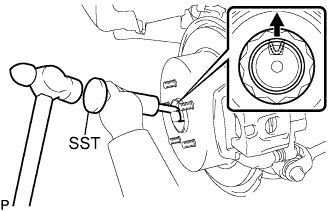

- SST
- 09930-00010
- NOTICE:
- Loosen the staked part of the nut completely, otherwise the screw of the drive shaft may be damaged.
While applying the brakes, remove the axle shaft nut.
| 3. SEPARATE REAR SPEED SENSOR |
Remove the bolt and separate the speed sensor from the axle carrier.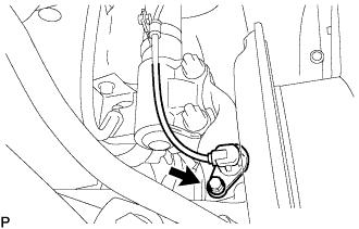
- NOTICE:
- Be careful not to damage the speed sensor.
- Prevent foreign matter from adhering to the speed sensor.
- Be careful not to damage the speed sensor.
| 4. SEPARATE REAR DISC BRAKE CALIPER ASSEMBLY |
Remove the 2 bolts and separate rear disc brake caliper assembly.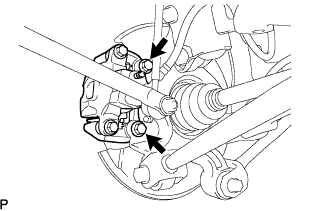
- NOTICE:
- Use a string or other device to keep the brake caliper from hanging down.
| 5. REMOVE REAR DISC |
Put matchmarks on the rear disc and the axle hub.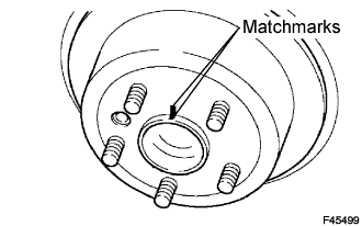
Release the parking brake, and remove the rear disc.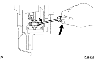
- HINT:
- If the disc cannot be removed easily, turn and press firmly the shoe adjuster until the wheel comes free.
| 6. SEPARATE PARKING BRAKE CABLE ASSEMBLY NO.3 |
Remove the nut, and separate the parking brake cable No.3.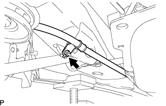
| 7. REMOVE REAR AXLE HUB AND BEARING ASSEMBLY |
Remove the 4 bolts and the rear axle hub and bearing assembly.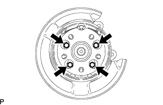
| 8. REMOVE REAR STRUT ROD ASSEMBLY |
Support the rear axle carrier with a wooden block placed between the jack and axle carrier.
Remove the 2 bolts, 2 nuts and strut rod assembly rear.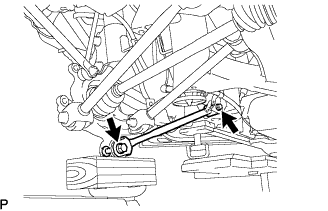
| 9. SEPARATE REAR SUSPENSION ARM ASSEMBLY NO.1 |
Remove the bolt and nut, and separate the rear suspension arm assembly No.1.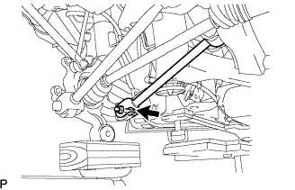
| 10. SEPARATE REAR SUSPENSION ARM ASSEMBLY NO.2 |
Remove the bolt and nut, and separate the rear suspension arm assembly No.2.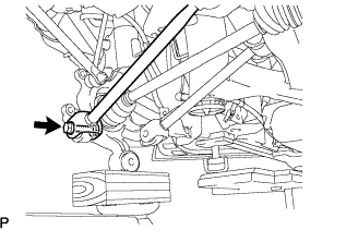
| 11. REMOVE REAR AXLE CARRIER SUB-ASSEMBLY |
Remove the 2 bolts and 2 nuts, and the rear axle carrier sub-assembly from the shock absorber.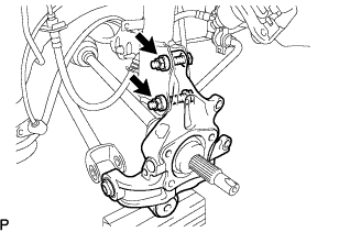
- NOTICE:
- Be careful not to damage the outboard joint boot.
- Be careful not to damage the speed sensor rotor.
- Be careful not to damage the outboard joint boot.
| 12. REMOVE REAR DRIVE SHAFT ASSEMBLY |
Put matchmarks on the rear drive shaft assembly and differential side gear shaft.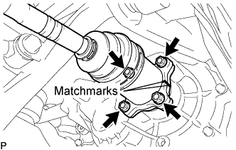
Remove the 4 nuts, washers and rear drive shaft assembly.