INSTALLATION
Removal / installation
| 1. INSTALL PARKING BRAKE PEDAL |

Install the parking brake pedal with the bolt and 2 nuts.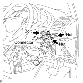

- Torque:
- Bolt:
- 24 N*m{ 245 kgf*cm , 18 ft.*lbf }
- Nut:
- 21 N*m{ 214 kgf*cm , 16 ft.*lbf }
Connect the connector and clamp.
Install the parking brake No.1 cable assembly to the body with the 2 nuts and 2 bolts.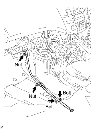
- Torque:
- Bolt:
- 8.5 N*m{ 87 kgf*cm , 75 in.*lbf }
- Nut:
- 6.0 N*m{ 61 kgf*cm , 53 in.*lbf }
Install the parking brake equalizer to the parking brake No.1 cable assembly.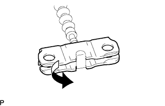
Slide the rubber boot back as shown in the illustration.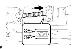
Connect the parking brake No.2 and No.3 cable assemblies to the parking brake equalizer.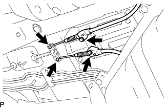
Install the parking brake No.2 and No.3 cable assemblies with the 2 bolts.
- Torque:
- 8.5 N*m{ 87 kgf*cm , 75 in.*lbf }
| 2. INSTALL AIR DUCT NO.1 |
Engage the 3 claws and install the air duct No.1.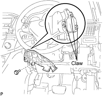
Install the bolt.
- Torque:
- 9.8 N*m{ 100 kgf*cm , 88 in.*lbf }
| 3. INSTALL CONSOLE BOX DUCT NO.1 |
Install the console box duct No.1.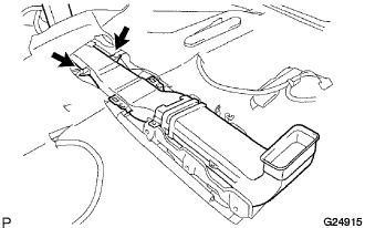
Engage the 2 clamps.
| 4. INSTALL CONSOLE COVER LOWER |
Connect the connector.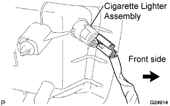
Engage the 3 clips and install the console cover lower.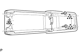
Install the 2 screws.
Install the clamp.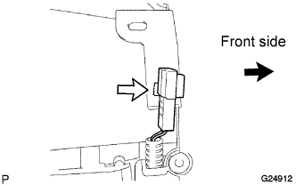
| 5. INSTALL REAR CONSOLE BOX |
Connect each of the clamp and the connector.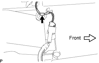
Keeping the rear console box pulled in the rear direction of the vehicle, install the 6 bolts from the left and right sides.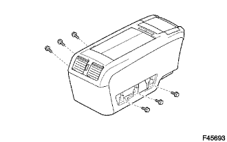
Connect the console box lock control cable assembly and install the rear console box.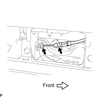
| 6. INSTALL CONSOLE BOX HOLE COVER |
Slide the front seat assemblies RH and LH forward.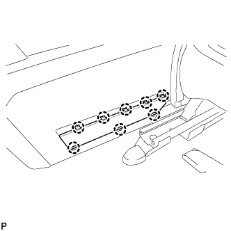
Slide the rear console box fully to the back end and install the console box hole cover.
| 7. INSTALL CONSOLE BOX NO.2 HOLE COVER |
- HINT:
- Use the same procedures for the console box No.2 hole cover and the console box hole cover.
| 8. INSTALL INSTRUMENT PANEL FINISH PANEL LOWER CENTER |
Engage the 2 clips.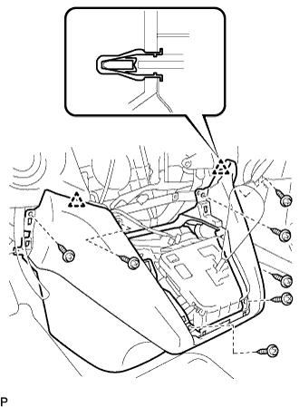
Install the 7 screws <C> and the instrument panel finish panel lower center.
| 9. INSTALL FLOOR CARPET COVER CENTER LH |
Slide the floor carpet cover center LH to the rear of the vehicle, and engage the 2 claws to the instrument panel finish panel lower center at the floor carpet cover center LH.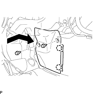
Install the 2 clips and the floor carpet cover center LH.
| 10. INSTALL FLOOR CARPET COVER CENTER RH |
- HINT:
- Use the same procedures for the RH side and the LH side.
| 11. INSTALL GLOVE COMPARTMENT DOOR ASSEMBLY |
Connect the connectors.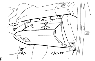
Install the 2 bolts <A>, the 2 screws <C>, and the glove compartment door assembly.
| 12. INSTALL INSTRUMENT PANEL NO.2 UNDER COVER SUB-ASSEMBLY |
Connect the connectors.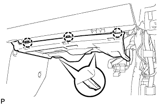
Engage the 3 claws and install the instrument panel No.2 under cover sub-assembly.
| 13. INSTALL COWL SIDE TRIM SUB-ASSEMBLY LH |
Install the 2 clips and the cowl side trim sub-assembly LH.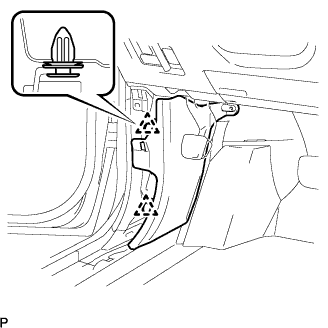
| 14. INSTALL FRONT DOOR SCUFF LH PLATE |
Connect the connector. (w/ illumination scuff plate)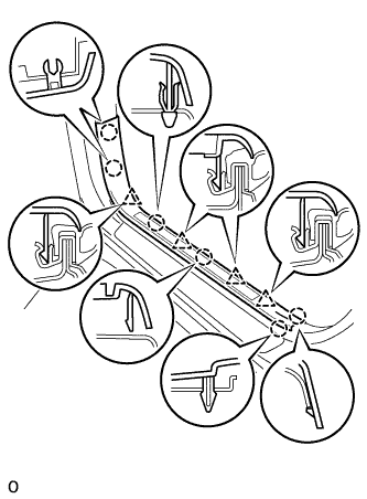
Engage the 6 claws and 4 clips, and install the front door scuff plate.
| 15. INSTALL INSTRUMENT PANEL FINISH PANEL SUB-ASSEMBLY LOWER |
Connect the connectors.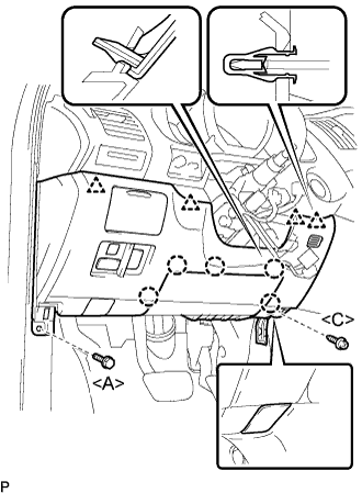
Engage the 5 claws and the 4 clips.
Connect the hood lock control cable assembly.
Install the bolt <A>, the screw <C>, and the instrument panel finish panel sub-assembly lower.
| 16. INSTALL COWL SIDE TRIM SUB-ASSEMBLY RH |
- HINT:
- Use the same procedures for the RH side and the LH side.
| 17. INSTALL FRONT DOOR SCUFF RH PLATE |
| 18. INSTALL INSTRUMENT PANEL FINISH PANEL LOWER |
Connect the connectors.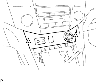
Engage the 2 clips and install the instrument panel finish panel lower.
| 19. INSTALL CONSOLE PANEL UPPER FRONT |
Engage the 4 clips and install the console panel upper front.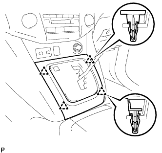
| 20. INSTALL SHIFT LEVER KNOB SUB-ASSEMBLY |
| 21. INSTALL FRONT SEAT ASSEMBLY |
Place the front seat assembly in the vehicle and align the adjuster pin with the hole on the vehicle side.
- NOTICE:
- When installing the passenger side front seat assembly, be careful not to step on the yaw rate sensor mounted on the floor under the seat.
Connect the connector.
Install the clamp.
Connect the negative battery cable.
Move the front seat assembly to the rearmost position by operating the slide and vertical power seat switch knob.
- NOTICE:
- Check that the seat is locked.
Temporarily install the front side of the front seat assembly with the 2 bolts.
Move the front seat assembly fully forward by operating the slide and vertical power seat switch knob.
- NOTICE:
- Check that the seat is locked.
Temporarily install the rear side of the front seat assembly with the 2 bolts.
Move the front seat assembly to the rearmost position by operating the slide and vertical power seat switch knob.
- NOTICE:
- Check that the seat is locked.
Fully tighten the 2 bolts on the front side of the front seat assembly in the order of the inner side bolt and then the outer side bolt.
- Torque:
- 37 N*m{ 377 kgf*cm , 27 ft.*lbf }
Move the front seat assembly fully forward by operating the slide and vertical power seat switch knob.
- NOTICE:
- Check that the seat is locked.
Fully tighten the 2 bolts on the rear side of the front seat assembly in the order of the inner side bolt and then the outer side bolt.
- Torque:
- 37 N*m{ 377 kgf*cm , 27 ft.*lbf }
| 22. INSTALL SEAT TRACK COVER LH |
| 23. INSTALL SEAT TRACK COVER RH |
| 24. INSTALL SEAT TRACK BRACKET COVER INNER FRONT LH |
| 25. INSTALL SEAT TRACK BRACKET COVER OUTER FRONT LH |
| 26. REMOVE REAR WHEEL |
| 27. ADJUST PARKING BRAKE SHOE CLEARANCE |
Temporarily install the hub nuts.
Remove the shoe adjusting hole plug.
Turn the shoe adjuster and expand the shoe until the disc locks.
Turn and contract the shoe adjuster until the disc can rotate smoothly.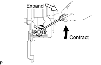
- Standard:
- Return 8 notches
Check that there is no brake drag against the shoe.
Install the shoe adjusting hole plug.
Remove the hub nuts.
| 28. INSTALL REAR WHEEL |
- Torque:
- 103 N*m{ 1,050 kgf*cm , 76 ft.*lbf }
| 29. INSPECT PARKING BRAKE PEDAL TRAVEL |
Fully depress the parking brake pedal and release it to engage the parking brake.
Depress the pedal to the floor again, and release it to disengage the parking brake.
Slowly depress the parking brake pedal to the floor, and count the number of clicks.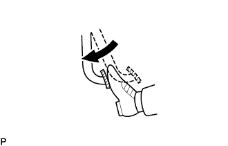
- Standard:
- 5 to 7 notches at 300 N (31 kgf, 68.3 lbf)
| 30. ADJUST PARKING BRAKE PEDAL TRAVEL |
Depress the parking brake pedal. Hold the wire adjusting No.1 nut using a wrench and loosen the lock nut.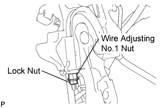
Release the parking brake pedal.
Turn the wire adjusting No.1 nut until the parking brake pedal travel meets the standard.
Hold the wire adjusting No.1 nut using a wrench or equivalent tool and tighten the lock nut.
- Torque:
- 6.0 N*m{ 61 kgf*cm , 53 in.*lbf }
Count the number of clicks after depressing and releasing the parking brake pedal 3 or 4 times.
Check whether the parking brake drags.
When operating the parking brake pedal, check that the parking brake indicator light comes on.
| 31. CONNECT CABLE TO NEGATIVE BATTERY TERMINAL |
| 32. PERFORM INITIALIZATION |
| 33. CHECK POWER SEAT FUNCTION |
Check the basic functions.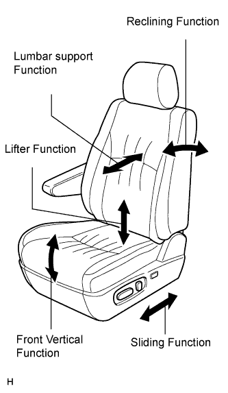
Operate the power seat switches and check the following seat functions:
- Sliding
- Reclining
- Front vertical
- Lifter
- Lumbar support
- Sliding
| 34. INSPECT SRS WARNING LIGHT (W/ SIDE AIRBAG) |
| 35. INSPECT SEAT HEATER OPERATION |