Sliding Roof ECU Power Source Circuit
Circuit diagnosis
DESCRIPTION
The sliding roof ECU receives signals from the sliding roof switch and activates the sliding roof. However, fuse, wire harness or sliding roof ECU malfunctions may cause the sliding roof system to stop operating.WIRING DIAGRAM
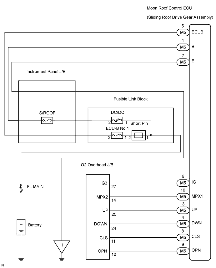

INSPECTION PROCEDURE
| 1. PERFORM ACTIVE TEST BY INTELLIGENT TESTER (SLIDING ROOF OPERATION) |

Select the Active Test, use the intelligent tester to generate a control command, and then check that the sliding roof operates normally.
- Sliding roof ECU:
Item
Test Details
Diagnostic Note
Sliding Roof
Operate sliding roof SLIDE CLOSE / TILT UP
CLOS / UP: Sliding roof SLIDE CLOSE or TILT UP operation occurs
OFF: Sliding roof is not operating
-
Sliding Roof
Operate sliding roof SLIDE OPEN/TILT DOWN
OPEN/DOWN: Sliding roof SLIDE OPEN or TILT DOWN operation occurs
OFF: Sliding roof is not operating
-
|
|
||||

| OK | ||
 |
||
| ||
| 2. INSPECT FUSE (S/ROOF, DC/DC, ECU-B No.1) |
Remove the S/ROOF fuse from the instrument panel J/B.
Remove the DC/DC fuse and ECU-B No.1 fuse from the fusible link block.
Measure the resistance of the fuses.
- Standard resistance:
- Below 1 Ω
|
|
||||

| OK | |
 |
| 3. CHECK SLIDING ROOF ECU (POWER SOURCE) |
Disconnect the M5 sliding roof ECU connector.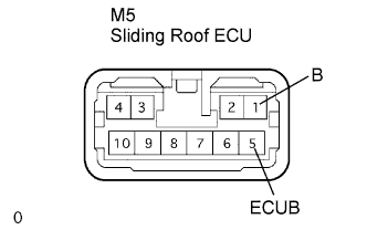
Check the voltage between the wire harness side connector and the body ground.
- Standard voltage:
Tester Connection
Specified Condition
M5-5 (ECUB) - Body ground
10 to 14 V
M5-1 (B) - Body ground
10 to 14 V
|
|
||||
| OK | |
|
| 4. CHECK SLIDING ROOF ECU (GROUND) |
Disconnect the M5 sliding roof ECU connector.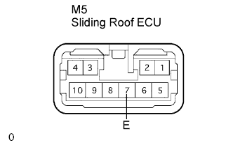
Check the resistance between the wire harness side connector and the body ground.
- Standard resistance:
Tester Connection
Specified Condition
M5-7 (E) - Body ground
Below 1 Ω
|
|
||||
| OK | ||
|
||
| ||