Sliding Roof Control Switch Circuit
Circuit diagnosis
DESCRIPTION
The sliding roof drive gear (sliding roof ECU) receives slide switch and tilt switch signals and drives its built-in motor.WIRING DIAGRAM
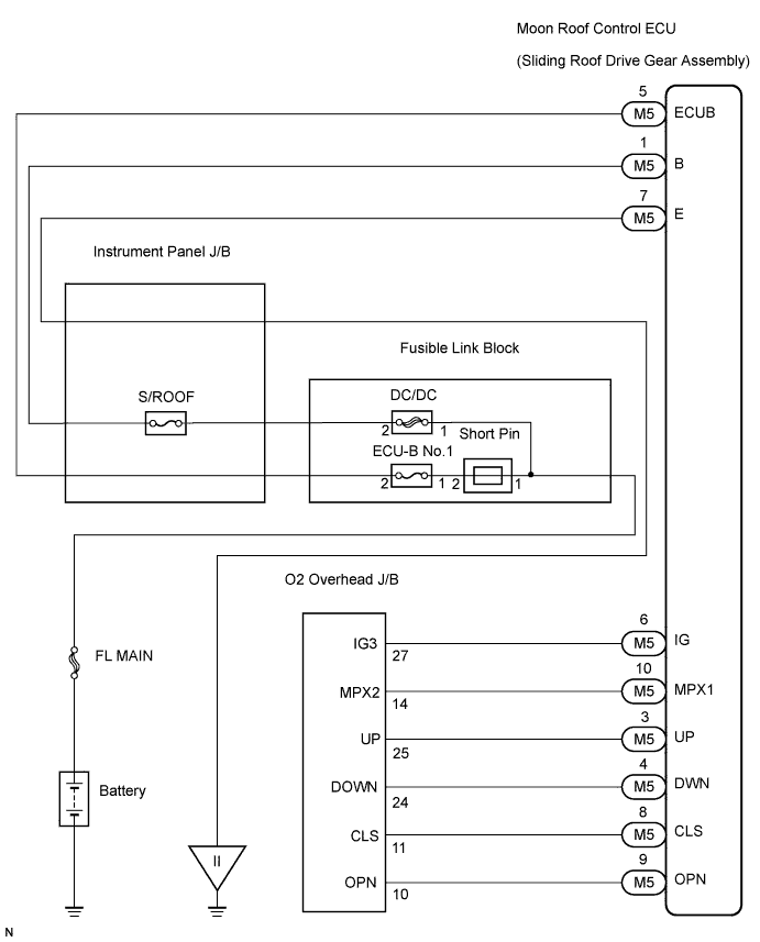

INSPECTION PROCEDURE
| 1. PERFORM ACTIVE TEST BY INTELLIGENT TESTER (SLIDING ROOF OPERATION) |

Select the Active Test, use the intelligent tester to generate a control command, and then check that the sliding roof slides open/close and tilts up/down.
- Sliding roof ECU:
Item
Test Details
Diagnostic Note
Sliding Roof
Operate sliding roof SLIDE CLOSE / TILT UP
CLOS / UP: Sliding roof SLIDE CLOSE or TILT UP operation occurs
OFF: Sliding roof is not operating
-
Sliding Roof
Operate sliding roof SLIDE OPEN / TILT DOWN
OPEN / DOWN: Sliding roof SLIDE OPEN or TILT DOWN operation occurs
OFF: Sliding roof is not operating
-
- OK:
- Sliding roof operates normally.
|
|
||||

| OK | |
 |
| 2. READ VALUE OF INTELLIGENT TESTER (SLIDING ROOF SWITCH) |
Use the Data List to check if the sliding roof switch is functioning properly.
- Sliding roof ECU:
Item
Measurement Item / Range (Display)
Normal Condition
Diagnostic Note
DOWN SWITCH
Tilt switch down signal / ON or OFF
ON: TILT DOWN switch is pressed
OFF: TILT DOWN switch is not pressed
-
UP SWITCH
Tilt switch up signal / ON or OFF
ON: TILT UP switch is pressed
OFF: TILT DOWN switch is not pressed
-
CLOSE SWITCH
Slide switch close signal / ON or OFF
ON: SLIDE CLOSE switch is pressed
OFF: SLIDE CLOSE switch is not pressed
-
OPEN SWITCH
Slide switch open signal / ON or OFF
ON: SLIDE OPEN switch is pressed
OFF: SLIDE OPEN switch is not pressed
-
- OK:
- When the switch is operating, the intelligent tester should display as shown in the table.
|
|
||||
| NG | |
|
| 3. INSPECT MAP LIGHT ASSEMBLY |
Check the tilt switch resistance.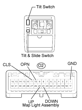
- Standard resistance:
Tester Connection
Switch Position
Specified Condition
O2-24 (DOWN) - O2-1 (GND)
DOWN
Below 1 Ω
O2-25 (UP) - O2-1 (GND)
UP
Below 1 Ω
Check the tilt & slide switch resistance.
- Standard resistance:
Tester Connection
Switch Condition
Specified Condition
O2-10 (OPN) - O2-1 (GND)
OPEN
Below 1 Ω
O2-11 (CLS) - O2-1 (GND)
CLOSE
Below 1 Ω
|
|
||||
| OK | |
|
| 4. CHECK WIRE HARNESS (SLIDING ROOF ECU - MAP LIGHT ASSEMBLY) |
Disconnect the M5 sliding roof ECU and O2 map light connectors.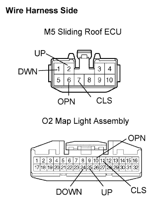
Check the resistance between the wire harness side connectors.
- Standard resistance:
Tester Connection
Specified Condition
M5-9 (OPN) - O2-10 (OPN)
Below 1 Ω
M5-8 (CLS) - O2-11 (CLS)
Below 1 Ω
M5-4 (DWN) - O2-24 (DOWN)
Below 1 Ω
M5-3 (UP) - O2-25 (UP)
Below 1 Ω
|
|
||||
| OK | ||
 |
||
| ||