P0420 After engine and TWC warmed up, and while vehicle driven within set vehicle and engine speeds, waveform of...
Diagnostic trouble codes
MONITOR DESCRIPTION
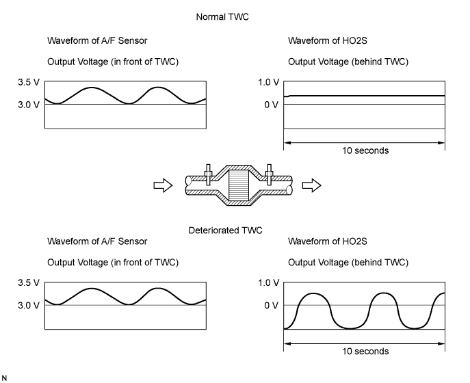
The ECM (Included in HV Control ECU) uses the two sensors, mounted in front of and behind the Three-way Catalytic Converter (TWC), to monitor its efficiency.The first sensor, the Air-Fuel Ration (A/F) sensor (sensor 1), sends pre-catalyst information to the ECM. The second sensor, the Heated Oxygen (HO2) sensor (sensor 2), sends post-catalyst information to the ECM. The ECM compares the information transmitted by these two sensors to determine the efficiency of the TWC performance and its ability to store oxygen.
When the TWC is functioning properly, the variation in the oxygen concentration in the exhaust gas, after it has passed through the TWC, is small. As a result, the voltage output of sensor 2 slowly alternates between the rich and lean signal voltages (shown in the illustration below). As the TWC performance efficiency deteriorates, its oxygen storage capacity decreases, and the variation in the oxygen concentration in the exhaust gas increases. As a result, the sensor voltage output fluctuates frequently.
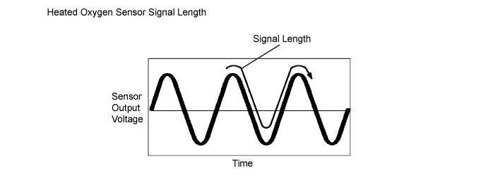
While the catalyst monitor is running, the ECM measures the signal length of both sensors 1 and 2, and calculate the ratio of the signal lengths to determine the extent of the TWC deterioration. If the deterioration level exceeds the preset threshold, the ECM interprets this as the TWC malfunction. The ECM then illuminates the MIL and sets the DTC.

| DTC No. |
DTC Detection Condition |
Trouble Area |
| P0420 |
After engine and TWC warmed up, and while vehicle driven within set vehicle and engine speeds, waveform of Heated Oxygen (HO2) sensor (bank 1 sensor 2) alternates frequently between rich and lean (2 trip detection logic) |
|
| P0430 |
After engine and catalyst are warmed up, and while vehicle is driven within set vehicle and engine speed ranges: Waveform of heated oxygen sensor (bank 2 sensor 2) alternates frequently between rich and lean (2 trip detection logic) |
|
- HINT:
- Bank 1 refers to the bank that includes cylinder No. 1
- Bank 2 refers to the bank that does not include cylinder No. 1
- Sensor 1 refers to the sensor closest to the engine assembly.
- Sensor 2 refers to the sensor farthest away from the engine assembly.
- Bank 1 refers to the bank that includes cylinder No. 1
CONDITIONING FOR SENSOR TESTING
- HINT:
- Perform the operation with the engine speeds and time durations described below prior to checking the waveforms of the A/F and HO2 sensors. This is in order to activate the sensors sufficiently to obtain the appropriate inspection results.
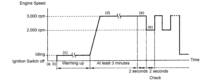
- (a) Connect the intelligent tester to the DLC3.
- (b) Put the engine in inspection mode (Click here).
- (c) Start the engine and warm it up with all the accessories switched OFF, until the engine coolant temperature stabilizes.
- (d) Run the engine at engine speed of between 2,500 rpm and 3,000 rpm for at least 3 minutes.
- (e) While running the engine at 3,000 rpm for 2 seconds and 2,000 rpm for 2 seconds, check the waveforms of the A/F and HO2 sensors using the tester or scan tool.
- NOTICE:
- The Air-Fuel Ratio (A/F) sensor has an output delay of a few seconds and the Heated Oxygen (HO2) sensor has a maximum output delay of approximately 20 seconds.
| Case |
A/F Sensor (Sensor 1) Output Voltage |
HO2 Sensor (Sensor 2) Output Voltage |
Main Suspected Trouble Area |
||
| 1 |
Injection Volume +25 % -12.5 % |
 |
Injection Volume +25 % -12.5 % |
|
- |
| Output Voltage More than 3.35 V Less than 3.0 V |
 |
Output Voltage More than 0.55 V Less than 0.4 V |
 |
||
| 2 |
Injection Volume +25 % -12.5 % |
|
Injection Volume +25 % -12.5 % |
|
|
| Output Voltage Almost no reaction |
 |
Output Voltage More than 0.55 V Less than 0.4 V |
|
||
| 3 |
Injection Volume +25 % -12.5 % |
|
Injection Volume +25 % -12.5 % |
|
|
| Output Voltage More than 3.35 V Less than 3.0 V |
|
Output Voltage Almost no reaction |
|
||
| 4 |
Injection volume +25 % -12.5 % |
|
Injection Volume +25 % -12.5 % |
|
|
| Output Voltage Almost no reaction |
|
Output Voltage Almost no reaction |
|
||
INSPECTION PROCEDURE
- HINT:
- Read freeze frame data using the intelligent tester. The ECM records vehicle and driving condition information as freeze frame data the moment a DTC is stored. When troubleshooting, freeze frame data can help determine if the vehicle was running or stopped, if the engine was warmed up or not, if the air-fuel ratio was LEAN or RICH, and other data from the time the malfunction occurred.
| 1. CHECK ANY OTHER DTCS OUTPUT (IN ADDITION TO DTC P0420 AND/OR P0430) |

Connect the intelligent tester to the DLC3.
Turn the ignition switch ON and turn the tester ON.
Enter the following menus: Powertrain / Engine / DTC.
Read DTCs.
- Result:
Display (DTC output)
Proceed to
P0420 and/or P0430
A
P0420 and/or P0430 and other DTCs
B
- HINT:
- If any DTCs other than P0420 or P0430 are output, troubleshoot those DTCs first.
|
|
||||

| A | |
 |
| 2. PERFORM ACTIVE TEST USING INTELLIGENT TESTER (A/F CONTROL) |
Connect the intelligent tester to the DLC3.
Put the engine in inspection mode (Click here).
Start the engine and turn the tester ON.
Warm up the engine at engine speed of 2,500 rpm for approximately 90 seconds.
On the tester, enter the following menus: Powertrain / Engine / Active Test / Control the Injection Volume for A/F Sensor.
Perform the A/F Control operation with the engine in an idling condition (press the Right or Left button to change the fuel injection volume.).
Monitor the output voltages of the A/F and HO2 sensors (AFS B1S1 and O2S B1S2 or AFS B2S1 and O2S B2S2) displayed on the tester.
- HINT:
- The A/F Control operation lowers the fuel injection volume by 12.5 % or increases the injection volume by 25 %.
- Each sensor reacts in accordance with increases and decreases in the fuel injection volume.
- The A/F Control operation lowers the fuel injection volume by 12.5 % or increases the injection volume by 25 %.
- Standard:
Tester Display
(Sensor)
Injection Volume
Status
Voltage
AFS B1S1 or AFS B2S1
(A/F)
+25 %
Rich
Less than 3.0
AFS B1S1 or AFS B2S1
(A/F)
-12.5 %
Lean
More than 3.35
O2S B1S2 or O2S B2S2
(HO2)
+25 %
Rich
More than 0.55
O2S B1S2 or O2S B2S2
(HO2)
-12.5 %
Lean
Less than 0.4
- Result:
Status
AFS B1S1
or
AFS B2S1
Status
O2S B1S2
or
O2S B2S2
A/F Condition and A/F and
HO2 Sensor Conditions
Misfire
Main Suspected Trouble Areas
Proceed to
Lean/Rich
Lean/Rich
Normal
-
- Three-Way Catalytic Converter (TWC)
- Gas leakage from exhaust system
A
Lean
Lean/Rich
A/F sensor malfunction
-
- A/F sensor
B
Rich
Lean/Rich
A/F sensor malfunction
May occur
- A/F sensor
B
Lean/Rich
Lean
HO2 sensor malfunction
-
- HO2 sensor
- Gas leakage from exhaust system
C
Lean/Rich
Rich
HO2 sensor malfunction
-
- HO2 sensor
- Gas leakage from exhaust system
C
Lean
Lean
Actual air-fuel ratio lean
May occur
- Extremely rich or lean actual air-fuel ratio
- Gas leakage from exhaust system
A
Rich
Rich
Actual air-fuel ratio lean
-
- Extremely rich or lean actual air-fuel ratio
- Gas leakage from exhaust system
A
- Three-Way Catalytic Converter (TWC)
|
|
||||
|
|
||||
| A | |
|
| 3. CHECK FOR EXHAUST GAS LEAKAGE |
- OK:
- No gas leakage.
|
|
||||
| OK | ||
 |
||
| ||