P0351 No IGF signal to ECM while engine running (1 trip detection logic)
Diagnostic trouble codes
DESCRIPTION
- HINT:
- These DTCs indicate malfunctions relating to the primary circuit.
- IF DTC P0351 is set, check No. 1 ignition coil circuit.
- IF DTC P0352 is set, check No. 2 ignition coil circuit.
- IF DTC P0353 is set, check No. 3 ignition coil circuit.
- IF DTC P0354 is set, check No. 4 ignition coil circuit.
- IF DTC P0355 is set, check No. 5 ignition coil circuit.
- IF DTC P0356 is set, check No. 6 ignition coil circuit.
- These DTCs indicate malfunctions relating to the primary circuit.
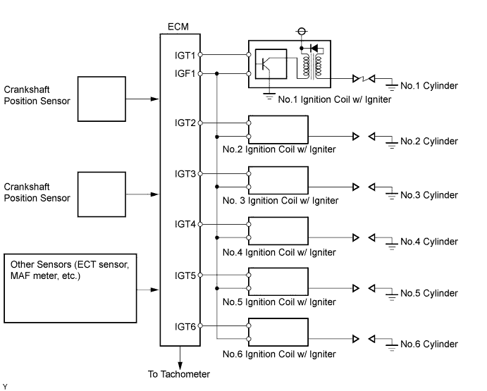
The DIS is a 1-cylinder ignition system in which each cylinder is ignited by one ignition coil and spark plug is connected to the end of each secondary wiring. A powerful voltage, generated in the secondary wiring, is applied directly to each spark plug. The sparks of the spark plugs pass from the center electrode to the ground electrodes.
The ECM (Included in HV Control ECU) determines the ignition timing and transmits the ignition signals (IGT) to each cylinder. Using the IGT signal, the ECM turns the power transistor inside the igniter on and off. The power transistor, in turn, switches on and off the current to the primary coil. When the current to the primary coil is cut off, a powerful voltage is generated in the secondary coil. This voltage is applied to the spark plugs, causing them to spark inside the cylinders. As the ECM cuts the current to the primary coil, the igniter sends back an ignition confirmation signal (IGF) to the ECM, for each cylinder ignition.

| DTC No. |
DTC Detection Condition |
Trouble Area |
| P0351 P0352 P0353 P0354 P0355 P0356 |
No IGF signal to ECM while engine running (1 trip detection logic) |
|
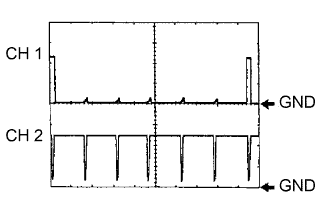
While cranking or idling the engine, check the waveform between terminals IGT (1 to 6) and E1, and IGF1 and E1 of the HV Control ECU connector.
| Item |
Content |
| Terminals |
CH1: IGT1, IGT2, IGT3, IGT4, IGT5, IGT6 - E1 CH2: IGF1 - E1 |
| Equipment Settings |
2 V/Division, 20 ms/DIvision |
| Conditions |
Cranking or idling |
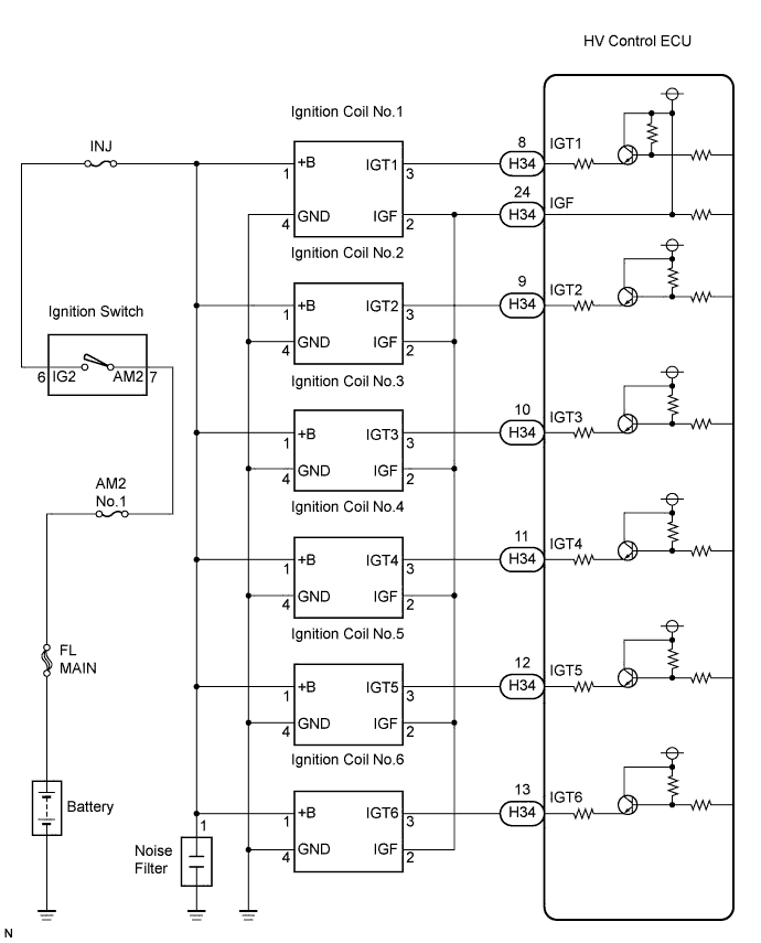
WIRING DIAGRAM
INSPECTION PROCEDURE
- HINT:
- Read freeze frame data using the intelligent tester. The ECM records vehicle and driving condition information as freeze frame data the moment a DTC is stored. When troubleshooting, freeze frame data can help determine if the vehicle was running or stopped, if the engine was warmed up or not, if the air-fuel ratio was LEAN or RICH, and other data from the time the malfunction occurred.
| 1. PERFORM SIMULATION TEST |

Clear the DTC(s) (Click here).
Change the arrangement of the ignition coils (with igniters).
- NOTICE:
- Do not change the location of the connectors.
Reform a simulation test.
- Result:
Display (DTC Output)
Proceed to
Same DTCs (that have been erased)
A
Other DTCs
B
|
|
||||

| A | |
 |
| 2. INSPECT IGNITION COIL ASSEMBLY (POWER SOURCE) |
Disconnect the I2, I3, I4, I5, I6 or I7 ignition coil connector.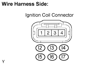
Turn the ignition switch ON.
Measure the voltage between the terminal of the wire harness side connector and body ground.
- Standard voltage:
Tester Connection
Specified Condition
I2-1 - Body ground
9 to 14 V
I3-1 - Body ground
9 to 14 V
I4-1 - Body ground
9 to 14 V
I5-1 - Body ground
9 to 14 V
I6-1 - Body ground
9 to 14 V
I7-1 - Body ground
9 to 14 V
Measure the resistance between the wire harness side connectors.
- Standard resistance:
Tester Connection
Specified Condition
I2-4 - Body ground
Below 1 Ω
I3-4 - Body ground
Below 1 Ω
I4-4 - Body ground
Below 1 Ω
I5-4 - Body ground
Below 1 Ω
I6-4 - Body ground
Below 1 Ω
I7-4 - Body ground
Below 1 Ω
|
|
||||
| OK | |
|
| 3. CHECK HARNESS AND CONNECTOR (IGNITION COIL ASSEMBLY - HV CONTROL ECU) |
Disconnect the I2, I3, I4, I5, I6 or I7 ignition coil connector.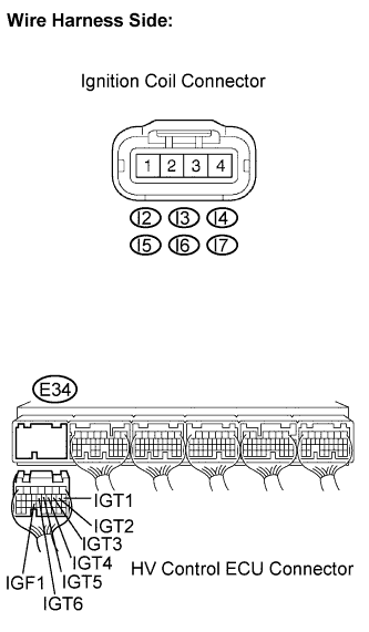
Disconnect the HV Control ECU H34 connectors.
Measure the resistance between the wire harness side connectors.
- Standard resistance (Check for open):
Tester Connection
Specified Condition
IGT1 (I2-3) - IGT1 (H34-8)
Below 1 Ω
IGT2 (I3-3) - IGT2 (H34-9)
Below 1 Ω
IGT3 (I4-3) - IGT3 (H34-10)
Below 1 Ω
IGT4 (I5-3) - IGT4 (H34-11)
Below 1 Ω
IGT5 (I6-3) - IGT5 (H34-12)
Below 1 Ω
IGT6 (I7-3) - IGT6 (H34-13)
Below 1 Ω
- Standard resistance (Check for short):
Tester Connection
Specified Condition
IGT1 (I2-3) - IGT1 (H34-8) - Body ground
10 kΩ or higher
IGT2 (I3-3) - IGT2 (H34-9) - Body ground
10 kΩ or higher
IGT3 (I4-3) - IGT3 (H34-10) - Body ground
10 kΩ or higher
IGT4 (I5-3) - IGT4 (H34-11) - Body ground
10 kΩ or higher
IGT5 (I6-3) - IGT5 (H34-12) - Body ground
10 kΩ or higher
IGT6 (I7-3) - IGT6 (H34-13) - Body ground
10 kΩ or higher
- Standard resistance (Check for open):
Tester Connection
Specified Condition
IGF1 (I2-2) - IGF1 (H34-24)
Below 1 Ω
IGF2 (I3-2) - IGF1 (H34-24)
Below 1 Ω
IGF3 (I4-2) - IGF1 (H34-24)
Below 1 Ω
IGF4 (I5-2) - IGF1 (H34-24)
Below 1 Ω
IGF5 (I6-2) - IGF1 (H34-24)
Below 1 Ω
IGF6 (I7-2) - IGF1 (H34-24)
Below 1 Ω
- Standard resistance (Check for short):
Tester Connection
Specified Condition
IGF1 (I2-2) or IGF1 (H34-24) - Body ground
10 kΩ or higher
IGF2 (I3-2) or IGF1 (H34-24) - Body ground
10 kΩ or higher
IGF3 (I4-2) or IGF1 (H34-24)- Body ground
10 kΩ or higher
IGF4 (I5-2) or IGF1 (H34-24) - Body ground
10 kΩ or higher
IGF5 (I6-2) or IGF1 (H34-24) - Body ground
10 kΩ or higher
IGF6 (I7-2) or IGF1 (H34-24)- Body ground
10 kΩ or higher
|
|
||||
| OK | |
|
| 4. CHECK ECM (IGT1, IGT2, IGT3, IGT4, IGT5, IGT6, IGF1 SIGNAL) |
Inspect using an oscilloscope.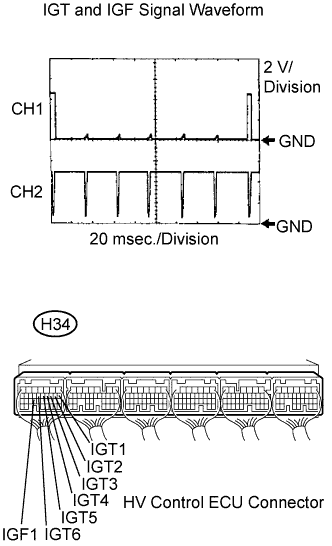
Put the engine in inspection mode (Click here).
Start the engine.
Check the waveform of the HV Control ECU connectors.
- Standard:
Tester Connection
Specified Condition
IGF1 (H34-24) - E1 (H31-5)
Correct waveform is shown
IGT1 (H34-8) - E1 (H31-5)
IGT2 (H34-9) - E1 (H31-5)
IGT3 (H34-10) - E1 (H31-5)
IGT4 (H34-11) - E1 (H31-5)
IGT5 (H34-12) - E1 (H31-5)
IGT6 (H34-13) - E1 (H31-5)
|
|
||||
| OK | |
|
| 5. CHECK IF DTC OUTPUT RECURS |
Clear the DTC (Click here).
Connect the intelligent tester to the DLC3.
Turn the ignition switch ON and turn the intelligent tester ON.
Enter the following menus: Powertrain / Engine / DTC.
Read DTC.
- Result:
Display (DTC Output)
Proceed to
P0351, P0352, P0353, P0354, P0355 and/or P0356 are output
A
No output
B
|
|
||||
| A | ||
 |
||
| ||