P0031 Air-Fuel Ratio (A/F) sensor heater (bank 1, 2 sensor 1) current less than 0.8 A (1 trip detection logic)
Diagnostic trouble codes
DESCRIPTION
- HINT:
- Although the DTC titles say oxygen sensor, these DTCs relate to the Air-Fuel Ratio (A/F) sensor.
- Sensor 1 refers to the sensor mounted in front of the Three-Way Catalytic Converter (TWC) and located near the engine assembly.
- Although the DTC titles say oxygen sensor, these DTCs relate to the Air-Fuel Ratio (A/F) sensor.
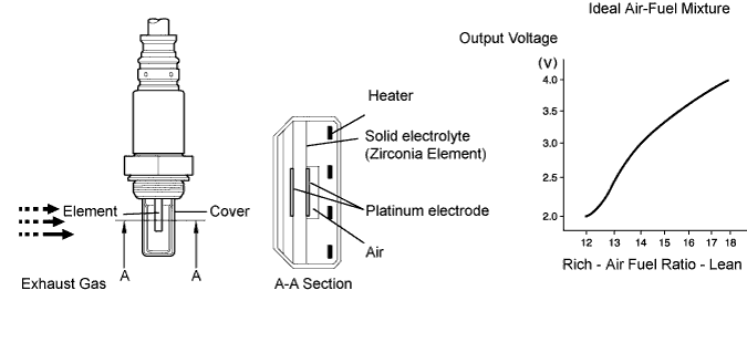
The A/F sensor is the planar type and is integrated with the heater, which heats the solid electrolyte (zirconia element). This heater is controlled by the ECM. When the intake air volume is low (the exhaust gas temperature is low), a current flows into the heater to heat the sensor, in order to facilitate accurate oxygen concentration detection. In addition, the sensor and heater portions are narrower than the conventional type. The heat generated by the heater is conducted to the solid electrolyte though the alumina, therefore the sensor activation is accelerated.
In order to obtain a high purification rate of the carbon monoxide (CO), hydrocarbon (HC) and nitrogen oxide (NOx) components in the exhaust gas, a TWC is used. For the most efficient use of the TWC, the air-fuel ratio must be precisely controlled so that it is always close to the stoichiometric level.
*: Value changes inside the ECM. Since the A/F sensor is the current output element, a current is converted to a voltage inside the ECM. Any measurements taken at the A/F sensor or ECM connectors will show a constant voltage.

- HINT:
- Although the DTC titles say the oxygen sensor, these DTCs relate to the Air-Fuel Ratio (A/F) sensor.
- Sensor 1 refers to the sensor mounted in front of the Three-Way Catalytic Converter (TWC) and located near the engine assembly.
- When any of these DTCs are set, the ECM (Included in HV Control ECU) enters fail-safe mode. The ECM turns off the A/F sensor heater in fail-safe mode. Fail-safe mode continues until the engine switch is turned off.
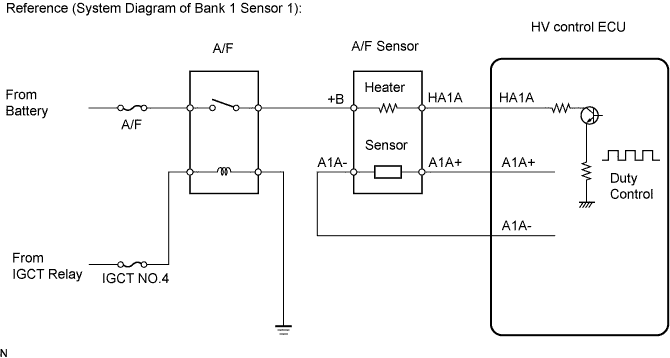
- The ECM provides a pulse width modulated control circuit to adjust the current through the heater. The A/F sensor heater circuit uses a relay on the B+ side of the circuit.
- Although the DTC titles say the oxygen sensor, these DTCs relate to the Air-Fuel Ratio (A/F) sensor.
| DTC No. |
DTC Detection Condition |
Trouble Area |
| P0031 P0051 |
Air-Fuel Ratio (A/F) sensor heater (bank 1, 2 sensor 1) current less than 0.8 A (1 trip detection logic) |
|
| P0032 P0052 |
Air-Fuel Ratio (A/F) sensor heater (bank 1, 2 sensor 1) current more than 10 A (1 trip detection logic) |
|
- HINT:
- Bank 1 refers to the bank that includes cylinder No. 1.
- Bank 2 refers to the bank that does not include cylinder No. 1.
- Sensor 1 refers to the sensor closest to the engine assembly.
- Sensor 2 refers to the sensor farthest away from the engine assembly.
- Bank 1 refers to the bank that includes cylinder No. 1.
WIRING DIAGRAM
Refer to DTC P2195 (Click here).INSPECTION PROCEDURE
- HINT:
- Read freeze frame data using the intelligent tester. The ECM records vehicle and driving condition information as freeze frame data the moment a DTC is stored. When troubleshooting, freeze frame data can help determine if the vehicle was running or stopped, if the engine was warmed up or not, if the air-fuel ratio was Lean or Rich, and other data from the time the malfunction occurred.
| 1. INSPECT AIR FUEL RATIO SENSOR (HEATER RESISTANCE) |

Disconnect the A4 or A5 A/F sensor connector.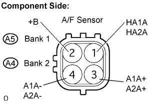
Measure the resistance between the terminals of the A/F sensor connector.
- Standard resistance:
Tester Connection
Specified Condition
HA1A, HA2A (1) - +B (2)
1.8 to 3.4 Ω at 20°C (68°F)
HA1A, HA2A (1) - A1A-, A2A- (4)
10 kΩ or higher
Reconnect the A/F sensor connector.
|
|
||||

| OK | |
 |
| 2. INSPECT A/F RELAY |
Remove the A/F relay from the engine room R/B.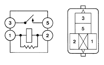
Measure the A/F relay resistance.
- Standard resistance:
Tester Connection
Specified Condition
3 - 5
10 kΩ or higher
3 - 5
Below 1 Ω
(when battery voltage applied to terminals 1 and 2)
Reinstall the A/F relay.
|
|
||||
| OK | |
|
| 3. INSPECT HV CONTROL ECU (HA1A AND HA2A TERMINALS) |
Turn the ignition switch ON.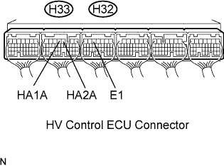
Measure the voltage between the terminals of the H33 and H32 HV Control ECU connector.
- Standard voltage:
Tester Connection
Specified Condition
HA1A (H33-4) - E1 (H32-5)
9 to 14 V
HA2A (H33-3) - E1 (H32-5)
9 to 14 V
- HINT:
- The HA1A means the A/F sensor bank 1 sensor 1.
- The HA2A means the A/F sensor bank 2 sensor 1.
- The HA1A means the A/F sensor bank 1 sensor 1.
|
|
||||
| NG | |
|
| 4. CHECK HARNESS AND CONNECTOR (A/F SENSOR - HV CONTROL ECU, A/F SENSOR - A/F RELAY) |
Check the harness and the connector between the HV Control ECU and the A/F sensor.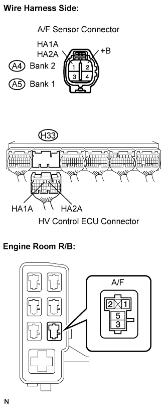
Disconnect the A4 or A5 A/F sensor connector.
Disconnect the H33 HV Control ECU connector.
Measure the resistance between the terminals of the A/F sensor and HV Control ECU.
- Standard resistance (Check for open):
Tester Connection
Specified Condition
HA1A (A5-1) - HA1A (H33-4)
Below 1 Ω
HA2A (A4-1) - HA2A (H33-3)
Below 1 Ω
- Standard resistance (Check for short):
Tester Connection
Specified Condition
HA1A (A5-1) or HA1A (H33-4) - Body ground
10 kΩ or higher
HA2A (A4-1) or HA2A (H33-3) - Body ground
10 kΩ or higher
Reconnect the A/F sensor connector.
Reconnect the HV Control ECU connector.
Check the harness and the connector between the A/F sensor and A/F relay.
Disconnect the A4 or A5 A/F sensor connector.
Remove the A/F relay from the engine room R/B.
Measure the resistance between the terminals of the A/F sensor and A/F relay.
- Standard resistance (Check for open):
Tester Connection
Specified Condition
+B (A5-2) - A/F relay (3)
Below 1 Ω
+B (A4-2) - A/F relay (3)
Below 1 Ω
- Standard resistance (Check for short):
Tester Connection
Specified Condition
+B (A5-2) or A/F HTR relay (3) - Body ground
10 kΩ or higher
+B (A4-2) or A/F HTR relay (3) - Body ground
10 kΩ or higher
Reconnect the A/F sensor connector.
Reinstall the A/F relay.
|
|
||||
| OK | ||
 |
||
| ||