P0037 Heated Oxygen (HO2) sensor heater current less than 0.25 A (1 trip detection logic)
Diagnostic trouble codes
DESCRIPTION
The heated oxygen sensor (HO2S) is used to monitor oxygen in the exhaust gas. For optimum catalyst operation, the air fuel mixture (air-fuel ratio) must be maintained near the ideal "stoichiometric" ratio. The HO2S output voltage changes suddenly in the vicinity of the stoichiometric ratio. The ECM (Included in HV Control ECU) adjusts the fuel injection time so that the air-fuel ratio is nearly stoichiometirc.The HO2S generates a voltage between 0.1 and 0.9 volts in response to oxygen in the exhaust gas. If the oxygen in the exhaust gas increases, the air-fuel ratio becomes "Lean". The ECM interprets Lean when the HO2S voltage is below 0.45 volts. If the oxygen in the exhaust gas decreases, the air-fuel ratio becomes "Rich". The ECM interprets Rich when the HO2S voltage is above 0.45 volts.
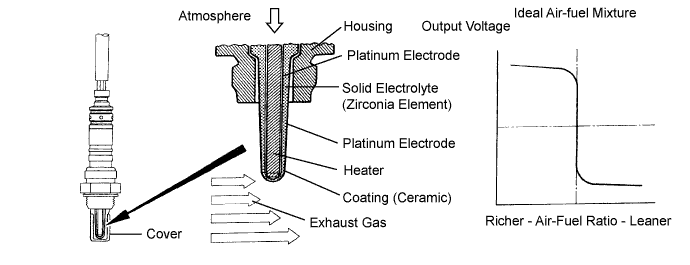

- HINT:
- Sensor 2 refers to the sensor mounted behind the Three-Way Catalytic Converter (TWC) and located far from the engine assembly.
- When any of these DTCs are set, the ECM (Included in HV Control ECU) enters fail-safe mode. The ECM turns off the Heated Oxygen (HO2) Sensor heater in fail-safe mode. Fail-safe mode continues until the engine switch is turned off.
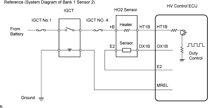
- The ECM provides a pulse width modulated control circuit to adjust the current through the heater. The HO2 sensor heater circuit uses a relay on the B+ side of the circuit.
- Sensor 2 refers to the sensor mounted behind the Three-Way Catalytic Converter (TWC) and located far from the engine assembly.
| DTC No. |
DTC Detection Condition |
Trouble Area |
| P0037 P0057 |
Heated Oxygen (HO2) sensor heater current less than 0.25 A (1 trip detection logic) |
|
| P0038 P0058 |
Heated Oxygen (HO2) sensor heater current more than 2 A (1 trip detection logic) |
|
- HINT:
- Bank 1 refers to the bank that includes cylinder No. 1.
- Bank 2 refers to the bank that does not include cylinder No. 1.
- Sensor 1 refers to the sensor closest to the engine assembly.
- Sensor 2 refers to the sensor farthest away from the engine assembly.
- Bank 1 refers to the bank that includes cylinder No. 1.
WIRING DIAGRAM
Refer to DTC P0136 (Click here).INSPECTION PROCEDURE
- HINT:
- If other DTCs relating to different systems that have terminal E2 as the ground terminal are output simultaneously, terminal E2 may have an open circuit.
- Read freeze frame data using the intelligent tester. The ECM records vehicle and driving condition information as freeze frame data the moment a DTC is stored. When troubleshooting, freeze frame data can help determine if the vehicle was moving or stationary, if the engine was warmed up or not, if the air-fuel ratio was lean or rich, and other data, from the time the malfunction occurred.
- If other DTCs relating to different systems that have terminal E2 as the ground terminal are output simultaneously, terminal E2 may have an open circuit.
| 1. INSPECT HEATED OXYGEN SENSOR (HEATER RESISTANCE) |

Disconnect the H20 or H11 heated oxygen (HO2) sensor connectors.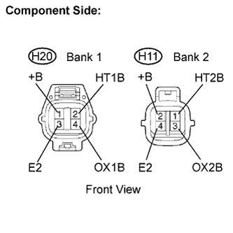
Measure the resistance between the terminals of the HO2 sensor connector.
- Standard resistance (Bank 1 sensor 2):
Tester Connection
Specified Condition
HT1B (2) - +B (1)
11 to 16 Ω at 20°C (68°F)
HT1B (2) - E2 (3)
10 kΩ or higher
- Standard resistance (Bank 2 sensor 2):
Tester Connection
Specified Condition
HT2B (1) - +B (2)
11 to 16 Ω at 20°C (68°F)
HT2B (1) - E2 (4)
10 kΩ or higher
Reconnect the HO2 sensor connector.
|
|
||||

| OK | |
 |
| 2. INSPECT IGCT RELAY |
Remove the IGCT relay from the engine room R/B.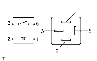
Inspect the IGCT relay.
- Standard resistance:
Terminal Connection
Specified Condition
3 - 5
10 kΩ or higher
3 - 5
Below 1 Ω
(When battery voltage applied to terminals 1 and 2)
Reinstall the IGCT relay.
|
|
||||
| OK | |
|
| 3. INSPECT HV CONTROL ECU (HT1B OR HT2B VOLTAGE) |
Turn the ignition switch ON.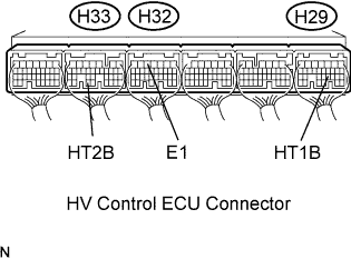
Measure the voltage between the terminals of the H29, H32 and H33 HV Control ECU connectors.
- Standard voltage:
Terminal Connection
Specified Condition
HT1B (H29-21) - E1 (H32-5)
9 to 14 V
HT2B (H33-33) - E1 (H32-5)
9 to 14 V
- HINT:
- The HT1B means the heated oxygen sensor bank 1 sensor 2.
- The HT2B means the heated oxygen sensor bank 2 sensor 2.
- The HT1B means the heated oxygen sensor bank 1 sensor 2.
|
|
||||
| NG | |
|
| 4. CHECK HARNESS AND CONNECTOR (HEATED OXYGEN SENSOR - IGCT NO.4 FUSE) |
Check the harness and connector between the HO2 sensor and IGCT fuse.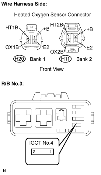
Disconnect the H11 or H20 HO2 sensor connector.
Remove the IGCT No.4 fuse from the R/B No.3.
Measure the resistance between the terminals of the HO2 sensor and IGCT No.4 fuse.
- Standard resistance:
Terminal Connection
Specified Condition
+B (H20-1) - IGCT No.4 fuse (2)
Below 1 Ω
+B (H11-2) - IGCT No.4 fuse (2)
Below 1 Ω
- Standard resistance:
Terminal Connection
Specified Condition
+B (H20-1) or IGCT No.4 fuse (2) - Body ground
10 kΩ or higher
+B (H11-2) or IGCT No.4 fuse (2) - Body ground
10 kΩ or higher
Reconnect the HO2 sensor connector.
Reconnect the IGCT No.4 fuse.
|
|
||||
| OK | |
|
| 5. CHECK HARNESS AND CONNECTOR (HEATED OXYGEN SENSOR - HV CONTROL ECU) |
Check the harness and connector between the HV Control ECU and HO2 sensor.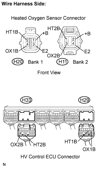
Disconnect the H20 or H11 HO2 sensor connector.
Remove the H29 and H33 HV Control ECU connector.
Measure the resistance between the terminals of the HO2 sensor and HV Control ECU.
- Standard resistance:
Terminal Connection
Specified Condition
HT1B (H20-1) - HT1B (H29-21)
Below 1 Ω
HT2B (H11-2) - HT2B (H33-33)
Below 1 Ω
HT1B (H20-1) or HT1B (H29-21) - Body ground
10 kΩ or higher
HT2B (H11-2) or HT2B (H33-33) - Body ground
10 kΩ or higher
Reconnect the HO2 sensor connector.
Reconnect the HV Control ECU connector.
|
|
||||
| OK | ||
 |
||
| ||