Fuel Pump Control Circuit
Circuit diagnosis
DESCRIPTION
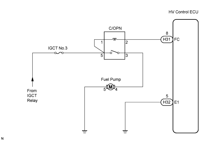
The fuel pump is operated by the engine control system according to the vehicle running condition. After the engine control system receives the engine start requirement signal from the HV control system, an NE signal comes in immediately when the engine is cranked by MG1 (basically, the fuel pump can operate while the NE signal is generated).The engine control system grounds the FC terminal line after receiving NE signal. It causes to energize the coil in the circuit opening relay, and the current flows to the fuel pump.
When the signal to stop the engine comes from the HV control system to the engine control system, or when the fuel cut operation is performed such as decelerating by the engine brake, the fuel pump is stopped.
WIRING DIAGRAM

INSPECTION PROCEDURE
| 1. PERFORM ACTIVE TEST BY INTELLIGENT TESTER (OPERATE C/OPN RELAY) |

Connect the intelligent tester to the DLC3.
Turn the ignition switch ON and turn the intelligent tester ON.
Enter the following menus: Powertrain / Engine / Active Test / Control the Fuel Pump/Speed.
Check the operation of the relay while operating it using the intelligent tester.
- OK:
- Operating noise can be heard from the relay.
|
|
||||

| NG | |
 |
| 2. INSPECT ECM POWER SOURCE CIRCUIT |
|
|
||||

| OK | |
|
| 3. INSPECT FUSE (IGCT NO.3 FUSE) |
Remove the IGCT No.3 fuse from the R/B No.3.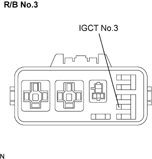
Measure the resistance in the IGCT No.3 fuse.
- Standard resistance:
- Below 1 Ω
|
|
||||
| OK | |
|
| 4. INSPECT C/OPN RELAY |
Remove the integration relay from the R/B No.1.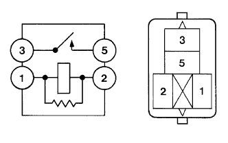
Measure the C/OPN relay resistance.
- Standard resistance:
Tester Connection
Specified Condition
3 - 5
10 kΩ or higher
3 - 5
Below 1 Ω
(Apply battery voltage between terminals 1 and 2)
|
|
||||
| OK | |
|
| 5. INSPECT HV CONTROL ECU (FC VOLTAGE) |
Turn the ignition switch ON.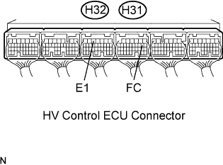
Measure the voltage between the terminals of the H31 and H32 HV Control ECU connectors.
- Standard voltage:
Tester Connection
Specified Condition
FC (H31-8) - E1 (H32-5)
9 to 14 V
|
|
||||
| NG | ||
 |
||
| ||
| 6. INSPECT FUEL PUMP |
Inspect fuel pump resistance.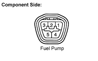
Measure the resistance between terminals 4 and 5.
- Standard resistance:
- 0.2 to 3.0 Ω at 20°C (68°F)
Inspect fuel pump operation.
Apply battery voltage to both the terminals. Check that the pump operates.
- NOTICE:
- These tests must be done quickly (within 10 seconds) to prevent the coil from burning out.
- Keep fuel pump as far away from the battery as possible.
- Always switch at the battery side.
- These tests must be done quickly (within 10 seconds) to prevent the coil from burning out.
|
|
||||
| OK | |
|
| 7. CHECK HARNESS AND CONNECTOR (FUEL PUMP - C/OPN RELAY) |
Check the harness and the connectors between the fuel pump and the C/OPN relay.
Disconnect the fuel pump connector.
Remove the C/OPN relay from the Engine Room R/B.
Measure the resistance between the wire harness side connectors.
- Standard resistance (Check for open):
Tester Connection
Specified Condition
Fuel pump (F18-4) - C/OPN relay (3)
Below 1 Ω
- Standard resistance (Check for short):
Tester Connection
Specified Condition
Fuel pump (F18-4) or F/PMP (3) - Body ground
10 kΩ or higher
Check the harness and the connectors between the fuel pump and the body ground.
Disconnect the fuel pump connector.
Measure the resistance between the wire harness side connector and the body ground.
- Standard resistance (Check for open):
Tester Connection
Specified Condition
Fuel pump (F18-5) - Body ground
10 kΩ or higher
|
|
||||
| OK | ||
|
||
| ||