MIL Circuit
Circuit diagnosis
DESCRIPTION
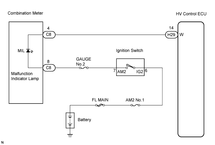
The MIL (Malfunction Indicator Lamp) is used to indicate malfunction detections by the ECM (Included in HV Control ECU).By turning the engine switch on (IG), power is supplied to the MIL circuit, and the ECM provides the circuit ground which illuminates the MIL.
The MIL operation can be checked visually: When the engine switch on (IG) is first turned to on, the MIL should be illuminated and should then turn off. If the MIL remains illuminated or is not illuminated, conduct the following troubleshooting procedure using the intelligent tester.
WIRING DIAGRAM

INSPECTION PROCEDURE
- HINT:
- Troubleshoot each trouble symptom in accordance with the chart below.
MIL remains illuminated
Start inspection from step 1
MIL not illuminated
Start inspection from step 3
| 1. CHECK WHETHER MIL TURNS OFF |

Connect the intelligent tester to the DLC3.
Turn the ignition switch ON.
Turn the tester ON.
Check whether any DTCs have been stored (Click here). Note them down if necessary.
Clear DTCs (Click here).
Check if the MIL turns off.
- OK:
- MIL should turn off.
|
|
||||

| NG | |
 |
| 2. CHECK HARNESS AND CONNECTOR (CHECK FOR SHORT IN WIRE HARNESS) |
Disconnect the H29 HV Control ECU connector.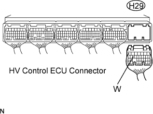
Turn the engine switch on (IG).
Check the MIL is not illuminated.
- OK:
- MIL is not illuminated.
Reconnect the HV Control ECU connector.
|
|
||||
| NG | ||
 |
||
| ||
| 3. CHECK THAT MIL IS ILLUMINATED |
Check if the MIL is illuminated when the engine switch is turnd to on.
- OK:
- MIL should be illuminated.
|
|
||||
| NG | |
|
| 4. INSPECT COMBINATION METER ASSEMBLY (MIL CIRCUIT) |
See the combination meter troubleshooting procedure (Click here).
|
|
||||
| OK | ||
|
||
| ||