TERMINALS OF ECU
System information
- HINT:
- This section describes the standard CAN values for all CAN related components.
| CAN J/C (CAN RH J/C, CAN CENTER J/C) |
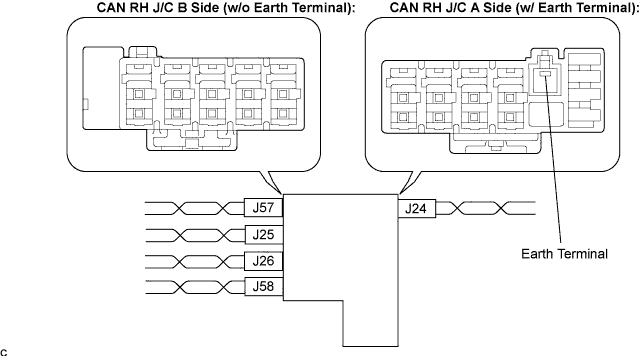
CAN RH J/C

- NOTICE:
- The connectors connected to the CAN J/C can be distinguished by the colors of the bus lines and the connecting side of the connector.
- The connectors can be connected to any cables on the same side.
- The connectors connected to the CAN J/C can be distinguished by the colors of the bus lines and the connecting side of the connector.
- Connector color:
CAN RH J/C connectors
(A side, w/ earth terminal)
Connector color
Skid control ECU (J24)
W
- Connector colors:
CAN RH J/C connectors
(B side, w/o earth terminal)
Connector color
HV control ECU (J57)
GR
CAN main bus line (J25) (bus line to connect CAN RH - CAN CENTER)
B
Yaw rate sensor (J26)
L
Television camera ECU (J58)
BR
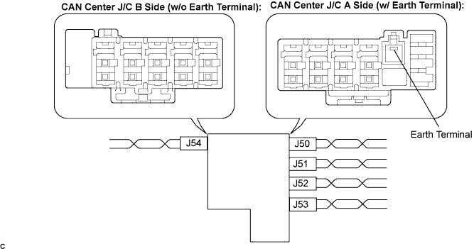
CAN Center J/C
- NOTICE:
- The connectors connected to the CAN J/C can be distinguished by the colors of the bus lines and the connecting side of the connector.
- The connectors can be connected to any cables on the same side.
- The connectors connected to the CAN J/C can be distinguished by the colors of the bus lines and the connecting side of the connector.
- Connector colors:
CAN Center J/C connectors
(A side, w/ earth terminal)
Connector color
Power steering ECU (J50)
BR
CAN main bus line (J51) (bus line to connect CAN center - CAN RH)
B
Network gateway ECU (J52)
L
DLC3 (J53)
W
- Connector colors:
CAN J/C connectors
(B side, w/o earth terminal)
Connector color
Steering sensor (J54)
GR
The terminals of the CAN J/C connectors.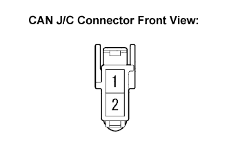
Terminal
Terminal symbol
1
CANH
2
CANL
Measure the resistance according to the value(s) in the table below.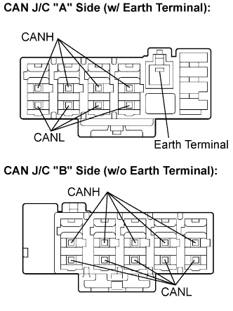
- Standard Resistance:
Terminals
Condition
Specified value
CANH - CANL
Disconnect the negative auxiliary battery cable
108 to 132 Ω
Wiring diagram for identifying CAN J/C connectors.
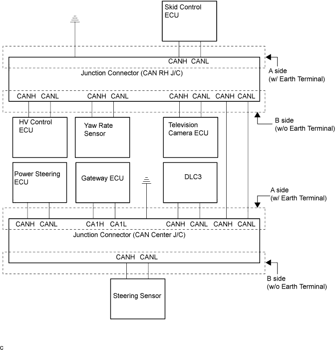
| DLC3 |
Measure the resistance according to the value(s) in the table below.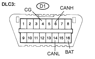
- Standard Resistance:
Terminals
Condition
Specified Condition
D1-6 (CANH) - D1-14 (CANL)
Disconnect the negative auxiliary battery cable
54 to 69 Ω
D1-6 (CANH) - D1-4 (CG)
Disconnect the negative auxiliary battery cable
1 kΩ or higher
D1-14 (CANL) - D1-4 (CG)
Disconnect the negative auxiliary battery cable
1 kΩ or higher
D1-6 (CANH) - D1-16 (BAT)
Disconnect the negative auxiliary battery cable
1 MΩ or higher
D1-14 (CANL) - D1-16 (BAT)
Disconnect the negative auxiliary battery cable
1 MΩ or higher
| SKID CONTROL ECU |
Disconnect the connectors from the skid control ECU.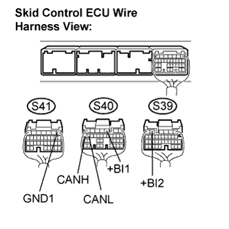
Measure the resistance according to the value(s) in the table below.
- Standard Resistance:
Terminals
Wiring Color
Condition
Specified Condition
S40-19 (CANH) - S40-18 (CANL)
B - W
Disconnect the negative auxiliary battery cable
54 to 69 Ω
S40-19 (CANH) - S41-1 (GND1)
B - W-B
Disconnect the negative auxiliary battery cable
1 kΩ or higher
S40-18 (CANL) - S41-1 (GND1)
W - W-B
Disconnect the negative auxiliary battery cable
1 kΩ or higher
S40-19 (CANH) - S40-3 (+BI1)
B - L
Disconnect the negative auxiliary battery cable
1 MΩ or higher
S40-18 (CANL) - S40-3 (+BI1)
W - L
Disconnect the negative auxiliary battery cable
1 MΩ or higher
S40-19 (CANH) - S39-5 (+BI2)
B - L-B
Disconnect the negative auxiliary battery cable
1 MΩ or higher
S40-18 (CANL) - S39-5 (+BI2)
W - L-B
Disconnect the negative auxiliary battery cable
1 MΩ or higher
| STEERING SENSOR |
Disconnect the connector from the steering sensor.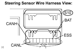
Measure the resistance according to the value(s) in the table below.
- Standard Resistance:
Terminals
Wiring Color (ECB)
Condition
Specified Condition
S10-10 (CANH) - S10-9 (CANL)
B - W
Disconnect the negative auxiliary battery cable
54 to 69 Ω
S10-10 (CANH) - S10-2 (ESS)
B - W-B
Disconnect the negative auxiliary battery cable
1 kΩ or higher
S10-9 (CANL) - S10-2 (ESS)
W - W-B
Disconnect the negative auxiliary battery cable
1 kΩ or higher
S10-10 (CANH) - S10-3 (BAT)
B - SB
Disconnect the negative auxiliary battery cable
1 MΩ or higher
S10-9 (CANL)- S10-3 (BAT)
W - SB
Disconnect the negative auxiliary battery cable
1 MΩ or higher
| YAW RATE SENSOR |
Disconnect the connector from the yaw rate sensor.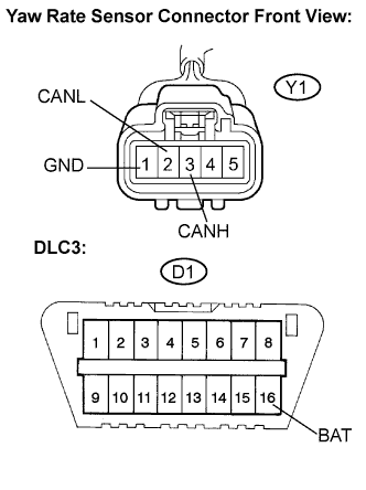
Measure the resistance according to the value(s) in the table below.
- Standard Resistance:
Terminals
Wiring Color
Condition
Specified Condition
Y1-3 (CANH) - Y1-2 (CANL)
B - W
Disconnect the negative auxiliary battery cable
54 to 69 Ω
Y1-3 (CANH) - Y1-1 (GND)
B - W-B
Disconnect the negative auxiliary battery cable
1 kΩ or higher
Y1-2 (CANL) - Y1-1 (GND)
W - W-B
Disconnect the negative auxiliary battery cable
1 kΩ or higher
Y1-3 (CANH) - D1-16 (BAT)
B - LG
Disconnect the negative auxiliary battery cable
1 MΩ or higher
Y1-2 (CANL) - D1-16 (BAT)
W - LG
Disconnect the negative auxiliary battery cable
1 MΩ or higher
| HV CONTROL ECU |
Disconnect the connectors from the HV control ECU.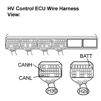
Measure the resistance according to the value(s) in the table below.
- Standard Resistance:
Terminals
Wiring Color
Condition
Specified Condition
H30-25 (CANH) - H30-33 (CANL)
B - W
Disconnect the negative auxiliary battery cable
54 to 69 Ω
H30-25 (CANH) - Body earth
B - Body earth
Disconnect the negative auxiliary battery cable
1 kΩ or higher
H30-33 (CANL) - Body earth
W - Body earth
Disconnect the negative auxiliary battery cable
1 kΩ or higher
H30-25 (CANH) - H29-1 (BATT)
B - GR
Disconnect the negative auxiliary battery cable
1 MΩ or higher
H30-33 (CANL) - H29-1 (BATT)
W - GR
Disconnect the negative auxiliary battery cable
1 MΩ or higher
| POWER STEERING ECU |
Disconnect the connector from the power steering ECU.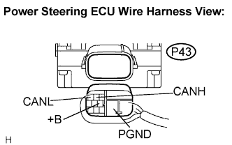
Measure the resistance according to the value(s) in the table below.
- Standard Resistance:
Terminals
Wiring Color
Condition
Specified Condition
P43-2 (CANH) - P43-3 (CANL)
B - W
Disconnect the negative auxiliary battery cable
54 to 69 Ω
P43-2 (CANH) - P43-5 (PGND)
B - B
Disconnect the negative auxiliary battery cable
1 kΩ or higher
P43-3 (CANL) - P43-5 (PGND)
W - B
Disconnect the negative auxiliary battery cable
1 kΩ or higher
P43-2 (CANH) - P43-6 (+B)
B - B-W
Disconnect the negative auxiliary battery cable
1 MΩ or higher
P43-3 (CANL) - P43-6 (+B)
W - B-W
Disconnect the negative auxiliary battery cable
1 MΩ or higher
| GATEWAY ECU |
Disconnect the connector from the gateway ECU.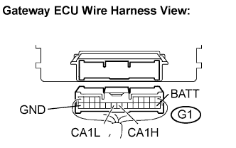
Measure the resistance according to the value(s) in the table below.
- Standard Resistance:
Terminals
Wiring Color
Condition
Specified Condition
G1-17 (CA1H) - G1-18 (CA1L)
B - W
Disconnect the negative auxiliary battery cable
54 to 69 Ω
G1-17 (CA1H) - G1-24 (GND)
B - W-B
Disconnect the negative auxiliary battery cable
1 kΩ or higher
G1-18 (CA1L) - G1-24 (GND)
W - W-B
Disconnect the negative auxiliary battery cable
1 kΩ or higher
G1-17 (CA1H) - G1-10 (BATT)
B - SB
Disconnect the negative auxiliary battery cable
1 MΩ or higher
G1-18 (CA1L) - G1-10 (BATT)
W - SB
Disconnect the negative auxiliary battery cable
1 MΩ or higher
| TELEVISION CAMERA ECU |
Disconnect the connector from the television camera ECU.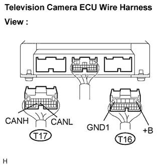
Measure the resistance according to the value(s) in the table below.
- Standard Resistance:
Terminals
Wiring Color
Condition
Specified Condition
T17-18 (CANH) - T17-17 (CANL)
B - W
Disconnect the negative auxiliary battery cable
54 to 69 Ω
T17-18 (CANH) - T16-6 (GND1)
B - W-B
Disconnect the negative auxiliary battery cable
1 kΩ or higher
T17-17 (CANL) - T16-6 (GND1)
W - W-B
Disconnect the negative auxiliary battery cable
1 kΩ or higher
T17-18 (CANH) - T16-1 (+B)
B - L
Disconnect the negative auxiliary battery cable
1 MΩ or higher
T17-17 (CANL) - T16-1 (+B)
W - L
Disconnect the negative auxiliary battery cable
1 MΩ or higher