P0705-757
Diagnostic trouble codes
DESCRIPTION
The park/neutral position switch sends 8 switch signals to the HV control ECU. The HV control ECU uses the signals to detect the shift lever position (P, R, N, D, or B) and control for such as the car moving forward and reverse.| DTC No. |
INF Code |
DTC Detection Condition |
Trouble Area |
| P0705 |
757 |
Park/neutral position switch pattern problem |
|
| P0705 |
758 |
Shifting malfunction (open circuit in MJ) |
|
| P0851 |
775 |
N signal circuit malfunction |
|
WIRING DIAGRAM
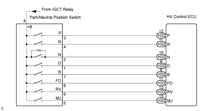

INSPECTION PROCEDURE
| 1. CLEAR DTC (HV) |

Connect the intelligent tester to the DLC3.
Turn the ignition switch to the ON position.
Select the following menu items: Powertrain / Hybrid Control / DTC.
Read and record the DTCs and freeze frame data.
Select the following menu items: Powertrain / Hybrid Control / DTC / Clear.
Clear the DTCs. (Click here)
| NEXT | |
 |
| 2. READ VALUE OF INTELLIGENT TESTER (SHIFT POSITION) |
Connect the intelligent tester to the DLC3.
Turn the ignition switch to the ON position.
Select the following menu items: Powertrain / Hybrid Control / Data List / Shift Position.
While slowly moving the shift lever from the P to B position, then back to P, read the data list (shift position) displayed on the intelligent tester.
- HINT:
- Be sure to slowly move the shift lever.
- Result:
Shift Position
ECU Data List
P
R
N
D
B
P
ON
OFF
OFF
OFF
OFF
R
OFF
ON
OFF
OFF
OFF
N
OFF
OFF
ON
OFF
OFF
D
OFF
OFF
OFF
ON
OFF
B
OFF
OFF
OFF
OFF
ON
RV
OFF
ON
OFF
OFF
OFF
FD
OFF
OFF
OFF
ON
ON
MJ
ON
ON
ON
ON
ON
Check that no DTCs are output.
- Result:
- DTCs P0705-757, P0705-758, and P0851-775 are not output.
|
|
||||

| NG | |
|
| 3. INSPECT HYBRID VEHICLE CONTROL ECU |
Turn the ignition switch to the ON position.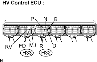
Measure the voltage according to the value(s) in the table below.
- Standard Voltage:
Shift Position
Tester Connection
Specified Condition
P
P (H32-12) - Body ground
10 to 14V
Any position except P
P (H32-12) - Body ground
0V
R
R (H32-11) - Body ground
10 to 14V
Any position except R
R (H32-11) - Body ground
0V
N
N (H32-10) - Body ground
10 to 14V
Any position except N
N (H32-10) - Body ground
1 to 2.5V
D
D (H32-9) - Body ground
10 to 14V
Any position except D
D (H32-9) - Body ground
0V
B
B (H32-8) - Body ground
10 to 14V
Any position except B
B (H32-8) - Body ground
0V
P, R, N, D, or B
MJ (H33-10) - Body ground
10 to 14V
D or B
FD (H33-11) - Body ground
10 to 14V
Any position except D and B
FD (H33-11) - Body ground
0V
R
RV (H33-12) - Body ground
10 to 14V
Any position except R
RV (H33-12) - Body ground
0V
|
|
||||
| NG | |
|
| 4. CHECK HARNESS AND CONNECTOR (PARK/NEUTRAL POSITION SWITCH - BODY GROUND) |
Disconnect the S35 park/neutral position switch connector.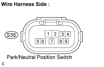
Turn the ignition switch to the ON position.
Measure the voltage according to the value(s) in the table below.
- Standard Voltage:
Tester Connection
Specified Condition
+B (S35-8) - Body ground
10 to 14V
- NOTICE:
- Turning the ignition switch to the ON position with the park/neutral position switch connector disconnected causes other DTCs to be stored. Clear the DTCs after performing the inspection.
|
|
||||
| OK | |
|
| 5. CHECK HARNESS AND CONNECTOR (HV CONTROL ECU - PARK/NEUTRAL POSITION SWITCH) |
Disconnect the H32 and H33 connectors from the HV control ECU.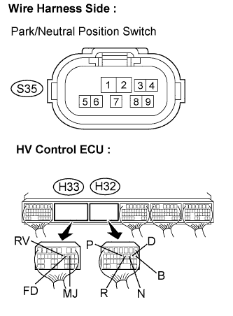
Disconnect the S35 park/neutral position switch connector.
Measure the voltage according to the value(s) in the table below when the ignition switch is in the ON position.
- Standard Voltage:
Tester Connection
Specified Condition
P (H32-12) - Body ground
Below 1 V
R (H32-11) - Body ground
Below 1 V
N (H32-10) - Body ground
Below 1 V
D (H32-9) - Body ground
Below 1 V
B (H32-8) - Body ground
Below 1 V
MJ (H33-10) - Body ground
Below 1 V
FD (H33-11) - Body ground
Below 1 V
RV (H33-12) - Body ground
Below 1 V
- NOTICE:
- Turning the ignition switch to the ON position with the park/neutral position switch connector and HV control ECU connectors disconnected causes other DTCs to be stored. Clear the DTCs after performing the inspection.
Turn the ignition switch off.
Measure the resistance according to the value(s) in the table below.
- Standard Resistance (Check for open):
Tester Connection
Specified Condition
P (H32-12) - P (S35-3)
Below 1 Ω
R (H32-11) - R (S35-4)
Below 1 Ω
N (H32-10) - N (S35-2)
Below 1 Ω
D (H32-9) - D (S35-1)
Below 1 Ω
B (H32-8) - B (S35-7)
Below 1 Ω
MJ (H33-10) - MJ (S35-5)
Below 1 Ω
FD (H33-11) - FD (S35-6)
Below 1 Ω
RV (H33-12) - RV (S35-9)
Below 1 Ω
- Standard Resistance (Check for short):
Tester Connection
Specified Condition
P (H32-12) or P (S35-3) - Body ground
10 kΩ or higher
R (H32-11) or R (S35-4) - Body ground
10 kΩ or higher
N (H32-10) or N (S35-2) - Body ground
10 kΩ or higher
D (H32-9) or D (S35-1) - Body ground
10 kΩ or higher
B (H32-8) or B (S35-7) - Body ground
10 kΩ or higher
MJ (H33-10) or MJ (S35-5) - Body ground
10 kΩ or higher
FD (H33-11) or FD (S35-6) - Body ground
10 kΩ or higher
RV (H33-12) or RV (S35-9) - Body ground
10 kΩ or higher
|
|
||||
| OK | ||
 |
||
| ||