Blower Motor Circuit
Circuit diagnosis
DESCRIPTION
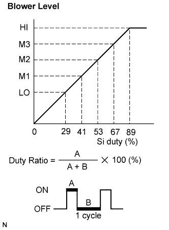

The blower motor is operated by signals from the A/C amplifier assembly. Blower motor speed signals are transmitted by changes in the duty ratio.
- The duty ratio is the ratio of the period of continuity in one cycle. For example, A is the period of continuity in one cycle, and B is the period of non-continuity.
WIRING DIAGRAM
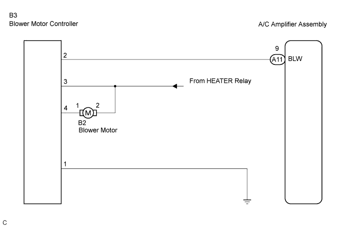
INSPECTION PROCEDURE
| 1. READ VALUE OF INTELLIGENT TESTER |

Connect the intelligent tester to the DLC3.
Turn the ignition switch ON and push the intelligent tester main switch on.
Select the item below in the DATA LIST, and read the display on the intelligent tester.
| Item |
Measurement Item/Display (Range) |
Normal Condition |
Diagnostic Note |
| BLOWER LEVEL |
Blower motor speed level /min.: Level 0 max.: Level 31 |
Changes depending on blower level |
- |
- OK:
- The display is as specified in the normal condition.
|
|
||||

| OK | ||
 |
||
| ||
| 2. PERFORM ACTIVE TEST BY INTELLIGENT TESTER |
Connect the intelligent tester to the DLC3.
Turn the ignition switch ON and push the intelligent tester main switch on.
Select the item below in the ACTIVE TEST and then check that the blower motor operates.
| Item |
Test Details/Display (Range) |
Diagnostic Note |
| BLOWER MOTOR |
Blower motor /min.: Level 0 max.: Level 31 |
- |
- OK:
- Blower motor operates and blower level changes.
|
|
||||
| OK | ||
|
||
| ||
| 3. PERFORM ACTUATOR CHECK |
Set the actuator check mode (Click here).
Press the blower switch to set the step operation.
Check for air flow level by hand.
| Display Code |
Blower Level |
| 0 |
0 |
| 1 |
1 |
| 2 |
17 |
| 3 |
17 |
| 4 |
17 |
| 5 |
17 |
| 6 |
17 |
| 7 |
17 |
| 8 |
17 |
| 9 |
31 |
- OK:
- Blower level changes in accordance with each display code.
|
|
||||
| OK | ||
|
||
| ||
| 4. CHECK HARNESS AND CONNECTOR (BLOWER MOTOR CONTROLLER - A/C AMPLIFIER ASSEMBLY) |
Disconnect the connector from the A/C amplifier assembly and the blower motor controller.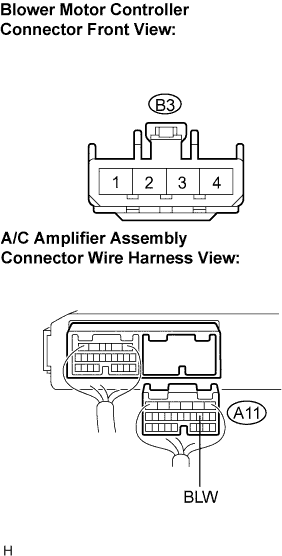
Measure the resistance according to the value(s) in the table below.
- Resistance:
Tester connection
(Symbols)
Condition
Specified condition
A11-9 (BLW) - B3-2
Always
Below 1 Ω
A11-9 (BLW) - Body ground
Always
10 kΩ or higher
|
|
||||

| OK | |
 |
| 5. CHECK HARNESS AND CONNECTOR (BLOWER MOTOR CONTROLLER - BODY GROUND) |
Measure the resistance according to the value(s) in the table below.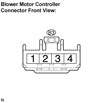
- Resistance:
Tester connection
Condition
Specified condition
B3-1 - Body ground
Always
Below 1 Ω
|
|
||||
| OK | |
|
| 6. CHECK HARNESS AND CONNECTOR (BLOWER MOTOR CONTROLLER - BLOWER MOTOR) |
Disconnect the connector from the blower motor.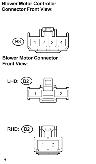
Measure the voltage according to the value(s) in the table below.
- Voltage:
Tester connection
Condition
Specified condition
B2-2 - Body ground
Ignition switch ON
Blower switch: ON
10 to 14 V
B3-3 - Body ground
Ignition switch ON
Blower switch: ON
10 to 14 V
B2-2 - Body ground
Ignition switch ON
Blower switch: OFF
Below 1 V
B3-3 - Body ground
Ignition switch ON
Blower switch: OFF
Below 1 V
|
|
||||
| OK | |
|
| 7. CHECK HARNESS AND CONNECTOR (BLOWER MOTOR CONTROLLER - BLOWER MOTOR) |
Measure the resistance according to the value(s) in the table below.
- Resistance:
Tester connection
Condition
Specified condition
B2-1 - B3-4
Always
Below 1 Ω
B2-1 - Body ground
Always
10 kΩ or higher
|
|
||||
| OK | |
|
| 8. INSPECT COOLING UNIT MOTOR SUB-ASSEMBLY W/FAN |
Remove the cooling unit motor sub-assembly w/ fan.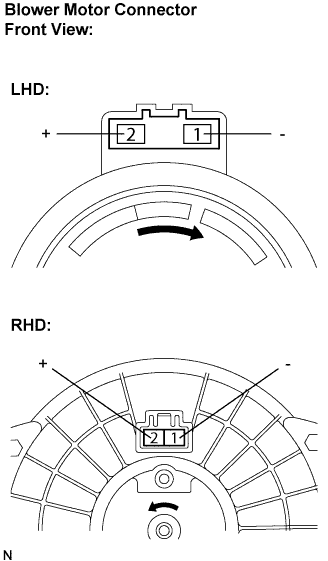
Connect the negative (-) lead connected to terminal 1 of the blower motor connector, the positive (+) lead to terminal 2.
- OK:
- Blower motor operates smoothly.
|
|
||||
| OK | |
|
| 9. INSPECT AIR CONDITIONING AMPLIFIER ASSEMBLY |
Reconnect the connector to the A/C amplifier assembly.
Remove the A/C amplifier assembly with the connectors still connected.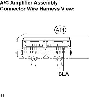
Turn the ignition switch to the ON position.
Blower speed switch is at "LO".
Measure the waveform between terminal BLW (A11-9) of the A/C amplifier assembly and body ground.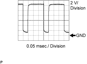
- OK:
- Waveform operate as shown in the illustration.
- HINT:
- Waveform cycle varies with the blower level.
|
|
||||
| OK | ||
|
||
| ||