Heater Relay Circuit
Circuit diagnosis
DESCRIPTION
The heater relay is turned on by signals from the A/C amplifier assembly. It supplies power to the blower motor controller.WIRING DIAGRAM
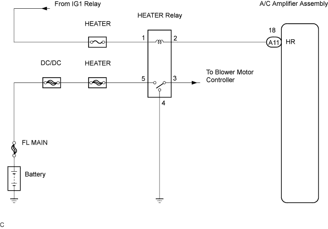

INSPECTION PROCEDURE
| 1. CHECK HEATER FUSE |

Remove the HEATER fuse from the instrument panel J/B.
Measure the resistance according to the value(s) in the table below.
- Resistance:
Tester item
Condition
Specified condition
HEATER fuse
Always
Below 1 Ω
|
|
||||

| OK | |
 |
| 2. INSPECT HEATER RELAY |
Remove the HEATER relay from R/B No.3.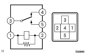
Measure the resistance according to the value(s) in the table below.
- Resistance:
Tester connection
Condition
Specified condition
3 - 5
Always
10 kΩ or higher
3 - 5
When battery voltage applied to terminals 1 and 2
Below 1 Ω
3 - 4
Always
Below 1 Ω
3 - 4
When battery voltage applied to terminals 1 and 2
10 kΩ or higher
|
|
||||
| OK | |
|
| 3. CHECK HARNESS AND CONNECTOR (A/C AMPLIFIER ASSEMBLY - BODY GROUND) |
Remove the A/C amplifier assembly with the connectors still connected.
Disconnect the connector from the A/C amplifier assembly.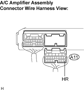
Measure the voltage according to the value(s) in the table below.
- Voltage:
Tester connection
(Symbols)
Condition
Specified condition
A11-18 (HR) - Body ground
Ignition switch position OFF
Blower switch position OFF
Below 1 V
A11-18 (HR) - Body ground
Ignition switch position ON
Blower switch position ON
Below 1 V
A11-18 (HR) - Body ground
Ignition switch position ON
Blower switch position OFF
10 to 14 V
|
|
||||
| OK | ||
 |
||
| ||