Heater Water Pump Circuit
Circuit diagnosis
DESCRIPTION
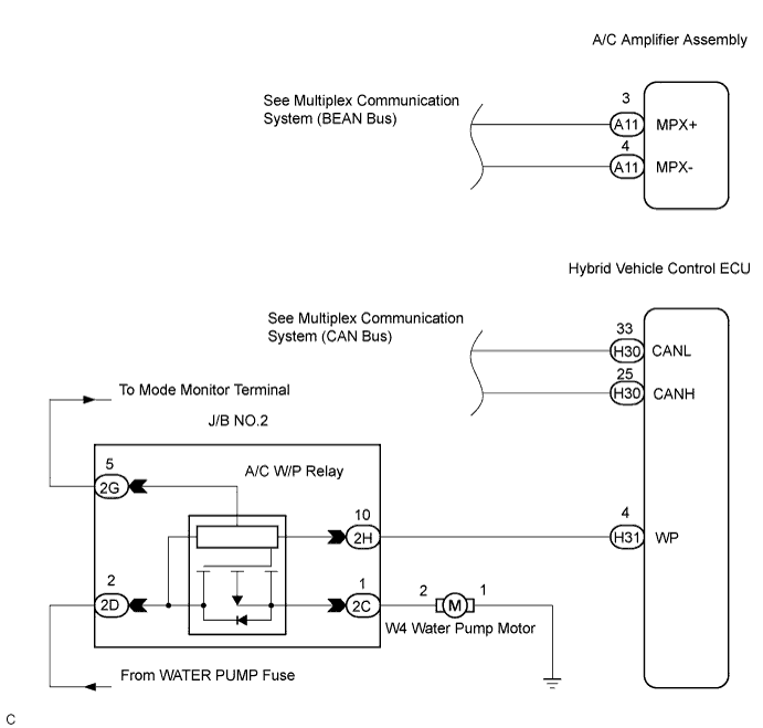
The heater water pump assembly sends engine coolant to the heater core assembly while the engine is stopped to prevent heater effectiveness from becoming low. Directed by the air conditioning amplifier assembly, the hybrid vehicle control ECU operates the water pump relay and drives the heater water pump assembly.System diagram of the power distributor (Click here).
System description of the power distributor (Click here).
WIRING DIAGRAM

INSPECTION PROCEDURE
| 1. PERFORM ACTIVE TEST BY INTELLIGENT TESTER |

Connect the intelligent tester to the DLC3.
Turn the ignition switch ON and push the intelligent tester main switch on.
Select the item below in the ACTIVE TEST and check that the relay operates.
ACTIVE TEST / AIR CONDITIONER Item
Test Details/Display
(Range)
Diagnostic Note
WATER PUMP
Water pump / OFF, ON
-
- OK:
- Heater water pump operates smoothly.
|
|
||||

| OK | ||
 |
||
| ||
| 2. PERFORM ACTIVE TEST BY INTELLIGENT TESTER |
Connect the intelligent tester to the DLC3.
Turn the ignition switch ON and push the intelligent tester main switch on.
Select the item below in the ACTIVE TEST and check that the water pump operates.
ACTIVE TEST / HYBRID CONTROL SYSTEM Item
Test Details/Display
(Range)
Diagnostic Note
WATER PUMP
Activate the Water Pump / OFF, ON
-
- OK:
- Heater water pump operates smoothly.
|
|
||||
| OK | ||
|
||
| ||
| 3. INSPECT MODE MONITOR TERMINAL |
Remove the cover of the fusible link block assembly.
Turn the ignition switch ON.
Measure the voltage when the following conditions are established.
Perform ACTIVE TEST by using the intelligent tester.
Operates the heater water pump.
Measure the voltage according to the value(s) in the table below.
- Result:
Result
Proceed to
Below 2 V
A
More than 4 V
B
|
|
||||
| A | |
 |
| 4. CHECK HARNESS AND CONNECTOR (J/B NO.2 - BODY GROUND) |
Disconnect the connector from J/B No.2 (2D).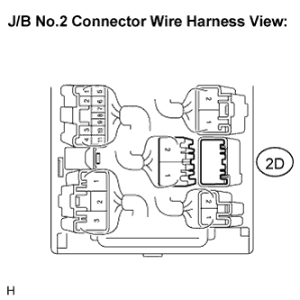
Turn the ignition switch ON.
Measure the voltage according to the value(s) in the table below.
- Voltage:
Tester connection
Condition
Specified condition
2D-2 - Body ground
Blower switch: ON
10 to 14 V
2D-2 - Body ground
Blower switch: OFF
Below 1 V
|
|
||||

| OK | |
|
| 5. INSPECT HEATER WATER PUMP ASSEMBLY |
Remove the heater water pump assembly.
Disconnect the connector from the heater water pump assembly.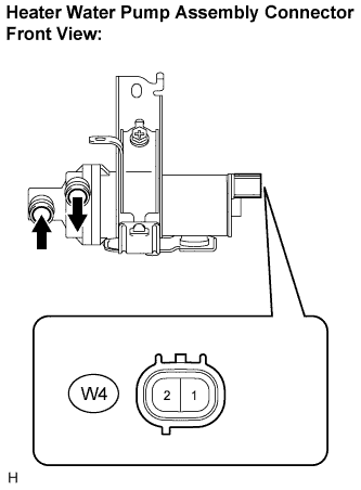
Connect the positive (+) lead to terminal 2 of the heater water pump assembly connector and the negative (-) lead to terminal 1.
- OK:
- Heater water pump operates smoothly.
- NOTICE:
- Complete operation within 10 seconds if there is no water in the heater water pump assembly.
|
|
||||
| OK | |
|
| 6. INSPECT J/B NO.2 (A/C W/P RELAY) |
Turn the ignition switch off.
Remove the J/B No.2.
Disconnect the connectors from the J/B No.2.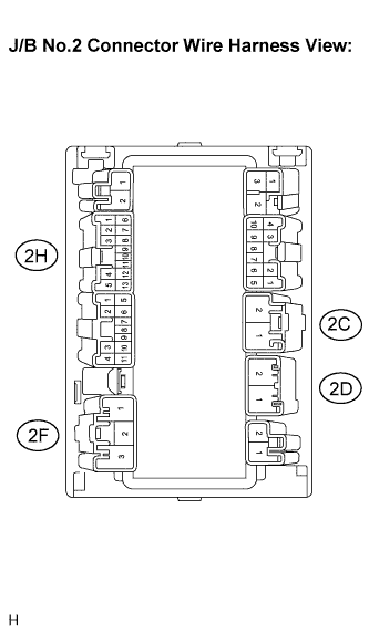
Connect the positive (+) lead from the battery to terminal 2D-2 (WPB) and the negative (-) lead to terminals 2H-13 (SGND) and 2F-1 (PGND).
Measure the voltage according to the value(s) in the table below.
- Voltage:
Tester connection
(Symbols)
Condition
Specified condition
2C-1 (WPL) - 2H-13 (SGND)
Always
Below 1 V
Connect the positive (+) lead from battery to terminal 2D-2 (WPB) and the negative (-) lead to terminals 2H-13 (SGND), 2F-1 (PGND) and 2H-10 (WP).
Measure the voltage according to the value(s) in the table below.
- Voltage:
Tester connection
(Symbols)
Condition
Specified condition
2C-1 (WPL) - 2H-13 (SGND)
Always
10 to 14 V
|
|
||||
| OK | ||
|
||
| ||
| 7. CHECK HARNESS AND CONNECTOR (HYBRID VEHICLE CONTROL ECU - BODY GROUND) |
Disconnect the connector from the hybrid vehicle control ECU.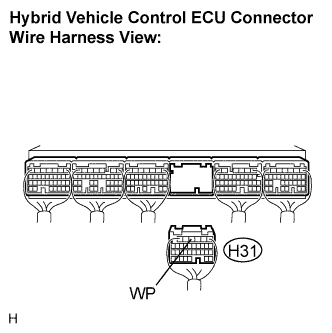
Measure the voltage according to the value(s) in the table below.
- Voltage:
Tester connection
(Symbols)
Condition
Specified condition
H31-4 (WP) - Body ground
Ignition switch: ON
10 to 14 V
H31-4 (WP) - Body ground
Ignition switch: OFF
Below 1 V
|
|
||||
| OK | |
|
| 8. INSPECT HYBRID VEHICLE CONTROL ECU |
Reconnect the connectors to the hybrid vehicle control ECU.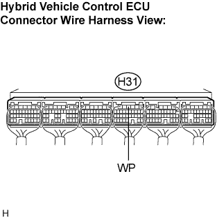
Turn the ignition switch ON.
Measure the voltage when these conditions are established.Test conditions:
Perform ACTIVE TEST by the intelligent tester.
Operates the heater water pump.
Measure the voltage according to the value(s) in the table below.
- Voltage:
Tester connection
(Symbols)
Condition
Specified condition
H31-4 (WP) - Body ground
Not operate the heater water pump
10 to 14 V
H31-4 (WP) - Body ground
Operate the heater water pump
Below 1 V
|
|
||||
| OK | |
|
| 9. INSPECT HEATER WATER PUMP ASSEMBLY |
Remove the heater water pump assembly.
Disconnect the connector from the heater water pump assembly.
Connect the positive (+) lead to terminal 2 of the heater water pump assembly connector and the negative (-) lead to terminal 1.
- OK:
- Heater water pump operates smoothly.
- NOTICE:
- Complete operation within 10 seconds if there is no water in the heater water pump assembly.
|
|
||||
| OK | |
|
| 10. INSPECT J/B NO.2 (A/C W/P RELAY) |
Turn the ignition switch off.
Remove the J/B No.2.
Disconnect the connectors from the J/B No.2.
Connect the positive (+) lead from the battery to terminal 2D-2 (WPB) and the negative (-) lead to terminals 2H-13 (SGND) and 2F-1 (PGND).
Measure the voltage according to the value(s) in the table below.
- Voltage:
Tester connection
(Symbols)
Condition
Specified condition
2C-1 (WPL) - 2H-13 (SGND)
Always
Below 1 V
Connect the positive (+) lead from battery to terminal 2D-2 (WPB) and the negative (-) lead to terminals 2H-13 (SGND), 2F-1 (PGND) and 2H-10 (WP).
Measure the voltage according to the value(s) in the table below.
- Voltage:
Tester connection
(Symbols)
Condition
Specified condition
2C-1 (WPL) - 2H-13 (SGND)
Always
10 to 14 V
|
|
||||
| OK | ||
|
||
| ||
| 11. CHECK HARNESS AND CONNECTOR (J/B NO.2 - BODY GROUND) |
Disconnect the connector from the J/B No.2 (2D).
Turn the ignition switch ON.
Measure the voltage according to the value(s) in the table below.
- Voltage:
Tester connection
Condition
Specified condition
2D-2 - Body ground
Blower switch: ON
10 to 14 V
2D-2 - Body ground
Blower switch: OFF
Below 1 V
|
|
||||
| OK | |
|
| 12. INSPECT J/B NO.2 (A/C W/P RELAY) |
Turn the ignition switch off.
Remove the J/B No.2.
Disconnect the connectors from the J/B No.2.
Connect the positive (+) lead from the battery to terminal 2D-2 (WPB) and the negative (-) lead to terminals 2H-13 (SGND) and 2F-1 (PGND).
Measure the voltage according to the value(s) in the table below.
- Voltage:
Tester connection
(Symbols)
Condition
Specified condition
2C-1 (WPL) - 2H-13 (SGND)
Always
Below 1 V
Connect the positive (+) lead from battery to terminal 2D-2 (WPB) and the negative (-) lead to terminals 2H-13 (SGND), 2F-1 (PGND) and 2H-10 (WP).
Measure the voltage according to the value(s) in the table below.
- Voltage:
Tester connection
(Symbols)
Condition
Specified condition
2C-1 (WPL) - 2H-13 (SGND)
Always
10 to 14 V
|
|
||||
| OK | ||
|
||
| ||