ABS Warning Light Remains ON
Circuit diagnosis
DESCRIPTION
The skid control ECU is connected to the combination meter via CAN and multiplex communications.If any of the following is detected, the ABS warning light remains on.
- The skid control ECU connectors are disconnected from the skid control ECU.
- There is a malfunction in the skid control ECU internal circuit.
- There is an open in the harness between the combination meter and the skid control ECU.
- HINT:
- There is a case that the intelligent tester cannot be used when the skid control ECU is abnormal.
WIRING DIAGRAM
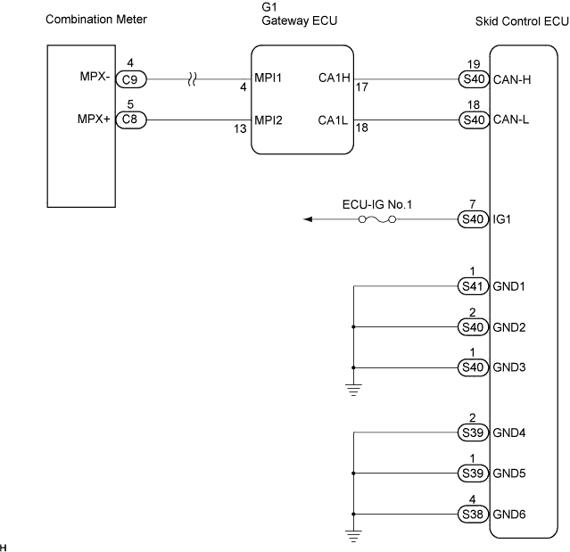

INSPECTION PROCEDURE
- NOTICE:
- When replacing the skid control ECU, perform initialization of linear solenoid valve and calibration (Click here).
| 1. INSPECT CAN COMMUNICATION SYSTEM |

Check if the CAN communication system DTC is output (Click here for LHD, Click here for RHD).
- Result:
Condition
Proceed To
DTC is not output
A
DTC is output
B
|
|
||||

| A | |
 |
| 2. INSPECT MULTIPLEX COMMUNICATION SYSTEM |
Check if the multiplex communication system DTC is output (Click here).
- Result:
Condition
Proceed To
DTC is not output
A
DTC is output
B
|
|
||||
| A | |
|
| 3. INSPECT IF SKID CONTROL ECU CONNECTOR IS SECURELY CONNECTED |
Check the skid control ECU connector's connecting condition.
- OK:
- The connector should be securely connected.
|
|
||||
| OK | |
|
| 4. INSPECT BATTERY |
Check the battery voltage.
- Voltage:
- 10 to 14 V
|
|
||||
| OK | |
|
| 5. INSPECT SKID CONTROL ECU (IG1 TERMINAL) |
Turn the ignition switch on.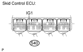
Measure the voltage according to the value(s) in the table below.
- Voltage:
Tester Connection
Condition
Specified Condition
S40-7 (IG1) - Body ground
Ignition switch on
10 to 14 V
|
|
||||
| OK | |
|
| 6. INSPECT SKID CONTROL ECU (GND TERMINAL) |
Measure the resistance according to the value(s) in the table below.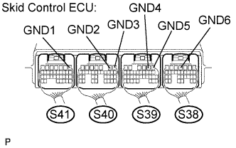
- Resistance:
Tester Connection
Specified Condition
S41-1 (GND1) - Body ground
Below 1 Ω
S40-2 (GND2) - Body ground
Below 1 Ω
S40-1 (GND3) - Body ground
Below 1 Ω
S39-2 (GND4) - Body ground
Below 1 Ω
S39-1 (GND5) - Body ground
Below 1 Ω
S38-4 (GND6) - Body ground
Below 1 Ω
|
|
||||
| OK | |
|
| 7. INSPECT COMBINATION METER ASSEMBLY |
Check the combination meter assembly (Click here).
- HINT:
- If troubleshooting has been carried out according to the PROBLEM SYMPTOMS TABLE, refer back to the table and proceed to the next step before replacing the part (Click here).
|
|
||||
| OK | ||
 |
||
| ||