ON-VEHICLE INSPECTION
Inspection
| CHECK COOLING FAN ECU (NO.1,NO.2) |

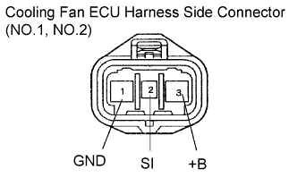  |
Inspect the input voltage.
Disconnect the cooling fan ECU connectors.
Turn the ignition switch on.
Measure the voltage between terminals +B and GND.
- Standard voltage:
- 8 to 15 V
- If the voltage is not as specified, check the fusible links, fuses, wire harness and fan relay.
Reconnect the connectors.
- HINT:
- Wire harness condition is diagnosed by cooling fan operation.
Cooling fan operation
Wire harness condition
Not in operation
Short
In continuous operation
Open
Check the HV control ECU power source.
Check RFC1 and RFC2 signal generation.
- NOTICE:
- Perform this inspection when coolant temperature is 82°C (180°F)
Connect an oscilloscope to terminals RFC1 (RFC2) and E1 of the HV control ECU.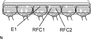
Check the signal generation and measure the current according to the value(s) in the table below.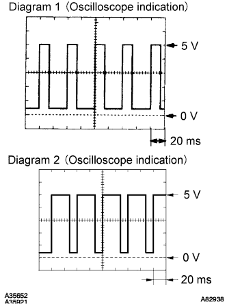
Condition
RFC1 (RFC2) signal generation
Fan operation
Fan operation
Engine stopped, IG switch ON
-
-
Not operate
Engine idling, A/C ON
-
-
Not operate
Engine idling, A/C ON
See Diagram 1
3 to 13 A
Operate
Engine idling, engine coolant temperature sensor connector disconnected
See Diagram 2
3 to 21 A
Operate (High speed)
- HINT:
- If RFC1 (RFC2) signal is not as specified, replace the HV control ECU.
- When the fan amperage has a problem even if the RFC1 (RFC2) signal that has no problem, replace the cooling fan ECU.
- If RFC1 (RFC2) signal is not as specified, replace the HV control ECU.