C1246/46
Diagnostic trouble codes
DESCRIPTION
The master cylinder pressure sensor and the wheel cylinder pressure sensor, which are built into the brake actuator, measure the master cylinder pressure and the wheel cylinder pressure and send to the skid control ECU.DTC C1281/81 can be deleted when the master cylinder pressure sensor sends a master cylinder pressure signal or the Test Mode ends. DTC C1281/81 is output only in the Test Mode.
| DTC No. |
INF Code |
DTC Detecting Condition |
Trouble Area |
| C1246/46 |
191 |
Sensor power source 1 (VCM1) voltage is less than 4.7 V or 5.3 V or more for at least 0.05 sec. |
|
| C1246/46 |
192 |
Ratio of master pressure sensor output voltage 1 (PMC1) to sensor power source (VCM1) is less than 5% or 90.5% or more for at least 0.05 sec. |
|
| C1246/46 |
194 |
Sensor power source 2 (VCM2) voltage is less than 4.7 V or 5.3 V or more for at least 0.05 sec. |
|
| C1246/46 |
195 |
Ratio of master pressure sensor output voltage 2 (PMC2) to sensor power source (VCM2) is less than 5% or 90.5% or more for at least 0.05 sec. |
|
| C1246/46 |
197 |
Master pressure sensor output voltage 1 (PMC1) is abnormal. |
|
| C1246/46 |
198 |
Master pressure sensor output voltage 2 (PMC2) is abnormal. |
|
| C1246/46 |
199 |
Master pressure sensor output 1 (PMC1) is not approx. 0 Mpa when not braking. |
|
| C1246/46 |
200 |
Master pressure sensor output 2 (PMC2) is not approx. 0 Mpa when not braking. |
|
| C1246/46 |
201 |
PMC1 and PMC2 voltages are different when braking. |
|
| C1246/46 |
202 |
Master pressure sensor 1 data (PMC1) is invalid. |
|
| C1246/46 |
205 |
Master pressure sensor 2 data (PMC2) is invalid. |
|
| C1364/61 |
221 |
Sensor power source 1 (VCM1) voltage is less than 4.7 V or 5.3 V or more for at least 0.05 sec. |
|
| C1364/61 |
222 |
Raio of FR right sensor output voltage (PFR) to sensor power source (VCM1) is less than 5% or 90.5% or more for at least 0.05 sec. |
|
| C1364/61 |
224 |
|
|
| C1364/61 |
225 |
Ratio of FR right sensor output voltage (PFR) to sensor power source (VCM1) is less than 90.5% for at least 0.1 sec. when self-diagnosis signal is output. |
|
| C1364/61 |
227 |
Sensor power source 2 (VCM2) voltage is less than 4.7 V or 5.3 V or more for at least 0.05 sec. |
|
| C1364/61 |
228 |
Ratio of FR left sensor output voltage (PFL) to sensor power source (VCM2) is less than 5% or 90.5% or more for at least 0.05 sec. |
|
| C1364/61 |
230 |
|
|
| C1364/61 |
231 |
Ratio of FR left sensor output voltage (PFL) to sensor power source (VCM2) is less than 90.5% for at least 0.1 sec. when self-diagnosis signal is output. |
|
| C1364/61 |
233 |
Sensor power source 2 (VCM2) voltage is less than 4.7 V or 5.3 V or more for at least 0.05 sec. |
|
| C1364/61 |
234 |
Ratio of RR right sensor output voltage (PRR) to sensor power source (VCM2) is less than 5% or 90.5% or more for at least 0.05 sec. |
|
| C1364/61 |
236 |
|
|
| C1364/61 |
237 |
Ratio of RR right sensor output voltage (PRR) to sensor power source (VCM2) is less than 90.5% for at least 0.1 sec. when self-diagnosis signal is output. |
|
| C1364/61 |
239 |
Sensor power source (VCM1) voltage is less than 4.7 V or 5.3 V or more for at least 0.05 sec. |
|
| C1364/61 |
240 |
Ratio of RR left sensor output voltage (PRL) to sensor power source (VCM1) is less than 5% or 90.5% or more for at least 0.05 sec. |
|
| C1364/61 |
242 |
|
|
| C1364/61 |
243 |
Ratio of RR left sensor output voltage (PRL) to sensor power source (VCM1) is less than 90.5% for at least 0.1 sec. when sel-diagnosis signal is output. |
|
WIRING DIAGRAM
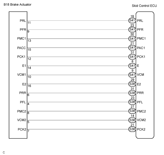

INSPECTION PROCEDURE
- NOTICE:
- When replacing the skid control ECU, perform initialization of linear solenoid valve and calibration (Click here).
| 1. CHECK HARNESS AND CONNECTOR (BETWEEN SKID CONTROL ECU AND BRAKE ACTUATOR ASSEMBLY) |

Disconnect the skid control ECU connector and brake actuator connector.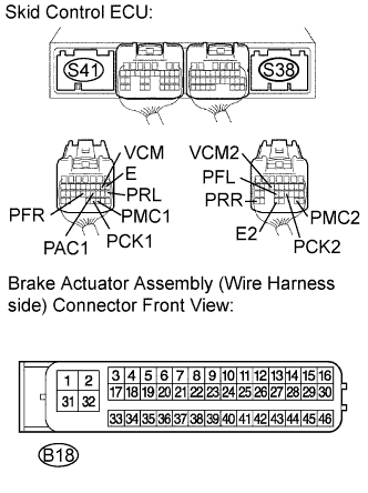
Measure the resistance according to the value(s) in the table below.
- Resistance:
Tester Connection
Specified Condition
S41-8 (E) - B18-14 (E1)
Below 1 Ω
S41-9 (VCM) - B18-10 (VCM1)
Below 1 Ω
S41-18 (PRL) - B18-11 (PRL)
Below 1 Ω
S41-21 (PAC1) - B18-15 (PACC)
Below 1 Ω
S41-23 (PFR) - B18-9 (PFR)
Below 1 Ω
S41-30 (PMC1) - B18-13 (PMC1)
Below 1 Ω
S41-31 (PCK1) - B18-12 (PCK1)
Below 1 Ω
S38-14 (VCM2) - B18-5 (VCM2)
Below 1 Ω
S38-21 (PCK2) - B18-7 (PCK2)
Below 1 Ω
S38-23 (PFL) - B18-4 (PFL)
Below 1 Ω
S38-27 (PMC2) - B18-8 (PMC2)
Below 1 Ω
S38-29 (E2) - B18-16 (E2)
Below 1 Ω
S38-31 (PRR) - B18-6 (PRR)
Below 1 Ω
Measure the resistance according to the value(s) in the table below.
- Resistance:
Tester Connection
Specified Condition
S41-8 (E) - Body ground
10 kΩ or higher
S41-9 (VCM) - Body ground
10 kΩ or higher
S41-18 (PRL) - Body ground
10 kΩ or higher
S41-21 (PAC1) - Body ground
10 kΩ or higher
S41-23 (PFR) - Body ground
10 kΩ or higher
S41-30 (PCM1) - Body ground
10 kΩ or higher
S41-31 (PCK1) - Body ground
10 kΩ or higher
S38-14 (VCM2) - Body ground
10 kΩ or higher
S38-21 (PCK2) - Body ground
10 kΩ or higher
S38-27 (PMC2) - Body ground
10 kΩ or higher
S38-29 (E2) - Body ground
10 kΩ or higher
S38-31 (PRR) - Body ground
10 kΩ or higher
|
|
||||

| OK | |
 |
| 2. INSPECT SKID CONTROL ECU |
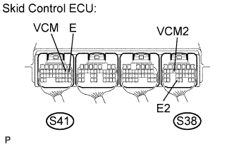 |
Connect the skid control ECU connector.
Measure the voltage according to the value(s) in the table below.
- HINT:
- Measure the voltage from the back side of the connector with the connector connected to the skid control ECU.
- Voltage:
Tester Connection
Condition
Specified Condition
S41-9 (VCM) - Body ground
Ignition switch ON
4.75 to 5.25 V
S38-14 (VCM2) - Body ground
Ignition switch ON
4.75 to 5.25 V
Measure the resistance according to the value(s) in the table below.
- Resistance:
Tester Connection
Specified Condition
S41-8 (E) - Body ground
Below 1 Ω
S38-29 (E2) - Body ground
Below 1 Ω
|
|
||||
| OK | |
|
| 3. READ VALUE OF INTELLIGENT TESTER (MASTER CYLINDER PRESSURE SENSOR) |
Connect the intelligent tester to the DLC3.
Select the DATA LIST mode on the intelligent tester.
ABS / VSC / TRAC: Item
Measurement Item /
Range (Display)
Normal Condition
Master Cylinder Sensor
Master cylinder pressure sensor 1 reading /
min.: 0 V, max.: 5 V
When brake pedal is released:
0.3 to 0.9 V
Master Cylinder Sensor 2
Master cylinder pressure sensor 2 reading /
min.: 0 V, max.: 5 V
When brake pedal is released:
0.3 to 0.9 V
Check the output value of the master cylinder pressure sensor on the intelligent tester display.
- OK:
- When the pedal is depressed, displayed voltage on the intelligent tester increases.
|
|
||||
| OK | |
|
| 4. READ VALUE OF INTELLIGENT TESTER (WHEEL CYLINDER PRESSURE SENSOR) |
Connect the pedal effort gauge.
Install the LSPV gauge (SST) and bleed air (Click here).
- SST
- 09709-29018
Connect the intelligent tester to the DLC3.
Select the DATA LIST mode on the intelligent tester.
ABS / VSC / TRAC: Item
Measurement Item /
Range (Display)
Normal Condition
FR W/C Sensor
Front Right pressure sensor /
min.: 0 V, max.: 5 V
When brake pedal is released:
0.3 to 0.9 V
FL W/C Sensor
Front Left pressure sensor /
min. 0 V, max.: 5 V
When brake pedal is released:
0.3 to 0.9 V
RR W/C Sensor
Rear Right pressure sensor /
min.: 0 V, max.: 5 V
When brake pedal is released:
0.3 to 0.9 V
RL W/C Sensor
Rear Left pressure sensor /
min. 0 V, max.: 5 V
When brake pedal is released:
0.3 to 0.9 V
Check the output value of the wheel cylinder pressure sensor at each fluid pressure during the ECB control.
- Voltage:
Front wheel cylinder pressure sensor Fluid Pressure
MPa (kgf/cm2, psi)
FR PRESS SENS
(DATA-LIST)
FL PRESS SENS
(DATA-LIST)
2.6 (26.5, 376.9)
0.85 to 1.15 V
0.85 to 1.15 V
6.3 (64.3, 914.5)
1.6 to 1.9 V
1.6 to 1.9 V
8.1 (82.6, 1174.8)
1.95 to 2.25 V
1.95 to 2.25 V
8.2 (83.6, 1189.0)
2.0 to 2.3 V
2.0 to 2.3 V
Rear wheel cylinder pressure sensor Fluid Pressure
MPa (kgf/cm2, psi)
RR PRESS SENS
(DATA-LIST)
RL PRESS SENS
(DATA-LIST)
2.7 (27.5, 391.1)
0.85 to 1.15 V
0.85 to 1.15 V
5.0 (51.0, 725.4)
1.35 to 1.65 V
1.35 to 1.65 V
|
|
||||
| OK | ||
 |
||
| ||