C1247/47
Diagnostic trouble codes
DESCRIPTION
The stroke sensor inputs the pedal stroke into the skid control ECU.DTC C1346/71 can be deleted when the brake pedal stroke sensor sends a stroke sensor signal or the Test Mode ends. DTC C1346/71 is output only in the Test Mode.
| DTC No. |
INF Code |
DTC Detecting Condition |
Trouble Area |
| C1247/47 |
171 |
Sensor power source voltage (VCSK) is 3.6 V or less or 4.95 V or more for at least 1.2 sec. |
|
| C1247/47 |
172 |
Ratio of sensor output voltage 1 (SKS1) to sensor power source voltage (VCSK) is less than 3% or 97% or more for at least 1.2 sec. |
|
| C1247/47 |
173 |
Ratio of sensor output voltage 2 (SKS2) to sensor power source voltage (VCSK) is less than 3% or 97% or more for at least 1.2 sec. |
|
| C1247/47 |
174 |
Sensor output 1 (SKS1) calculation value becomes 20 mm or more for at least 1.2 sec. at an interval of 0.006 sec. (changes due to interference). |
|
| C1247/47 |
175 |
Sensor output 2 (SKS2) calculation value becomes 20 mm or more for at least 1.2 sec. at an interval of 0.006 sec. (changes due to interference). |
|
| C1247/47 |
176 |
Zero point stored value (ratio to power source voltage) of sensor output 1 (SKS1) is 0.46 or more or 0.03 or less. |
|
| C1247/47 |
177 |
Zero point stored value (ratio to power source voltage) of sensor output 2 (SKS2) is 0.97 or more or 0.48 or less. |
|
| C1247/47 |
179 |
|
|
| C1247/47 |
180 |
|
|
| C1392/48 |
178 |
Zero point calibration of stroke sensor is unfinished. |
|
WIRING DIAGRAM
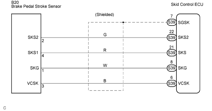

INSPECTION PROCEDURE
- NOTICE:
- When replacing the skid control ECU, perform initialization of linear solenoid valve and calibration (Click here).
| 1. CHECK BRAKE PEDAL |

Check that the brake pedal and the brake pedal stroke sensor are properly installed and that the pedal can be operated normally.
Check the brake pedal height.
- OK:
- The brake pedal is securely installed.
- The pedal height is within the specified range (Click here).
|
|
||||

| OK | |
 |
| 2. READ VALUE OF INTELLIGENT TESTER (BRAKE PEDAL STROKE SENSOR) |
Connect the intelligent tester to the DLC3.
Turn the ignition switch on.
Select the DATA LIST mode on the intelligent tester.
ABS / VSC / TRAC: Item
Measurement Item /
Range (Display)
Normal condition
Stroke Sensor
Stroke sensor /
min.:0 V, max.: 5 V
When brake pedal is released:
0.7 to 1.3 V
Stroke Sensor 2
Stroke sensor 2 /
min.: 0 V, max.: 5 V
When brake pedal is released:
3.7 to 4.3 V
Read the pedal stroke sensor voltage value on the intelligent tester screen.
- OK:
- The value displayed on the intelligent tester is within the normal range.
|
|
||||

| OK | |
|
| 3. PERFORM INITIALIZATION OF LINEAR SOLENOID VALVE AND CALIBRATION |
| NEXT | |
|
| 4. RECONFIRM DTC |
Clear the DTCs (Click here).
Turn the ignition switch on.
Check the same DTCs are recorded (Click here).
- Result:
Condition
Proceed To
DTC is output
A
DTC is not output
B
- HINT:
- This DTC may be memorized due to a malfunction in the connector terminal connection, etc.
|
|
||||
| A | |
|
| 5. CHECK HARNESS AND CONNECTOR (BETWEEN SKID CONTROL ECU AND BRAKE PEDAL STROKE SENSOR) |
Disconnect the skid control ECU connector and brake pedal stroke sensor connector.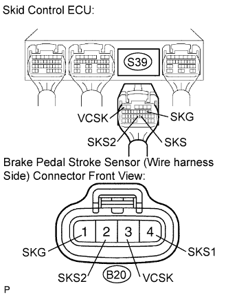
Measure the resistance according to the value(s) in the table below.
- Resistance:
Tester Connection
Specified Condition
S39-6 (VCSK) - B20-3 (VCSK)
Below 1 Ω
S39-8 (SKG) - B20-1 (SKG)
Below 1 Ω
S39-21 (SKS) - B20-4 (SKS1)
Below 1 Ω
S39-22 (SKS2) - B20-2 (SKS2)
Below 1 Ω
Measure the resistance according to the value(s) in the table below.
- Resistance:
Tester Connection
Specified Condition
S39-6 (VCSK) - Body ground
10 kΩ or higher
S39-8 (SKG) - Body ground
10 kΩ or higher
S39-21 (SKS) - Body ground
10 kΩ or higher
S39-22 (SKS2) - Body ground
10 kΩ or higher
|
|
||||
| OK | |
|
| 6. INSPECT SKID CONTROL ECU (VCSK, SKG TERMINAL) |
Measure the voltage according to the value(s) in the table below.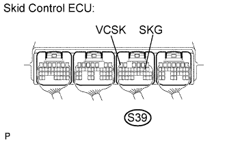
- HINT:
- Measure the voltage from the back side of the connector with the connector connected to the skid control ECU.
- Voltage:
Tester Connection
Specified Condition
S39-6 (VCSK) - S39-8 (SKG)
3.6 to 4.95 V
|
|
||||
| OK | |
|
| 7. INSPECT SKID CONTROL ECU (SKS1, SKS2 TERMINAL) |
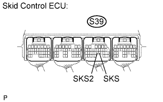 |
Connect the brake pedal stroke sensor connector.
Measure the voltage according to the value(s) in the table below.
- HINT:
- Measure the voltage from behind the connector with the connector connected to the skid control ECU.
- Slowly depress the brake pedal and check if the voltage between the skid control ECU terminal and body ground changes in accordance with the pedal operation.
- Measure the voltage from behind the connector with the connector connected to the skid control ECU.
- Voltage:
Tester Connection
Specified Condition
S39-21 (SKS) - Body ground
1.8 to 3.1 V
S39-22 (SKS2) - Body ground
1.8 to 3.1 V
|
|
||||
| OK | ||
 |
||
| ||